Advertisement
Available languages
Available languages
Quick Links
ISTRUZIONI PER L'USO E L'INSTALLAZIONE
INSTRUCTIONS POUR L'UTILISATION ET L'INSTALLATION
OPERATING AND INSTALLATION INSTRUCTIONS
GEBRAUCHSANWEISUNGEN UND INSTALLATION
Elettroriduttore reversibile per cancelli a battente - Moto-réducteur reversible pour portails à battant
Reversible actuator for leaf gates - Nicht Selbsthemmender Torantrieb für Flugeltore
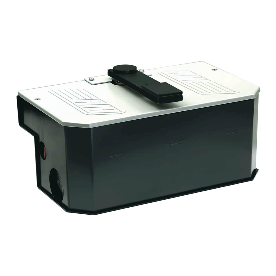
Mod.
Ø65
Ø35
Fig. 1
Controllo pre-installazione .......................................................................................pag.3
Caratteristiche Tecniche ..........................................................................................pag.3
Preparazione e cementazione cassa di fondazione .............................................pag.4-5
Regolazione finecorsa e frizione..............................................................................pag.6
Sblocco d'emergenza, Manutenzione .....................................................................pag.7
Funzionamento Accessori di Comando e di Sicurezza ..........................................pag.8
Dichiarazione di Conformità...................................................................................pag.27
Registro di Manutenzione ......................................................................................pag.28
Note ..................................................................................................................pag.29-30
Esploso MAGIC105° .............................................................................................pag.31
Esploso MAGIC180° .............................................................................................pag.32
Contrôle pré-installation...........................................................................................pag.9
Caractéristiques techniques ....................................................................................pag.9
Cimenter le caisson ..........................................................................................pag.10-11
Réglage du fin de course.......................................................................................pag.12
Déblocage d'urgence, Entretien ............................................................................pag.13
Fonctionnement des Accessoires de Commande et de Sécurité ..........................pag.14
Déclaration de conformité......................................................................................pag.27
Dossier d'entretien.................................................................................................pag.28
Note ..................................................................................................................pag.29-30
Vue éclatée MAGIC105° .......................................................................................pag.31
Vue éclatée MAGIC105° .......................................................................................pag.32
MAGIC
Misure in mm/inch
Mesures en mm/inch
INDICE
INDEX
1,96"
16,1"
4"
Measurements in mm/inch
Abmessungen in mm/inch
Checking before the Installation ............................................................................pag.15
Technical Features ................................................................................................pag.15
Motor and rack fitting ........................................................................................pag.16-17
Limit switch and clutch adjustment ........................................................................pag.18
Emergency release system, Maintenance ............................................................pag.19
Safety and Command Accessories........................................................................pag.20
Declaration of Compliance.....................................................................................pag.27
Maintenance log ....................................................................................................pag.28
Note ..................................................................................................................pag.29-30
Exploded view MAGIC105° ...................................................................................pag.31
Exploded view MAGIC180° ...................................................................................pag.32
Vor der Montage auszuführende Überprüfungen .................................................pag.21
Technische Eigenschaften.....................................................................................pag.21
Befestigung von Motor und Zahnstange...........................................................pag.22-23
Einstellung Endschalter und Rutschkupplung .......................................................pag.24
Notfall-Freigabe, Instandhaltung............................................................................pag.25
Sicherheits und Steuerzubehörs............................................................................pag.26
Konformitätserklärungen........................................................................................pag.27
Wartungsregister ...................................................................................................pag.28
Note ..................................................................................................................pag.29-30
Explosionszeichnungen MAGIC105° ....................................................................pag.31
Explosionszeichnungen MAGIC180° ....................................................................pag.32
Pag. 1 di 32
Ø35
3,1"
2"
6,4"
1,3"
2,3"
9,8"
INDEX
INDEX
I
F
GB
D
Ø65
Advertisement

Summary of Contents for Ribind MAGIC 105
- Page 1 Pag. 1 di 32 ISTRUZIONI PER L'USO E L’INSTALLAZIONE INSTRUCTIONS POUR L'UTILISATION ET L’INSTALLATION OPERATING AND INSTALLATION INSTRUCTIONS GEBRAUCHSANWEISUNGEN UND INSTALLATION Elettroriduttore reversibile per cancelli a battente - Moto-réducteur reversible pour portails à battant Reversible actuator for leaf gates - Nicht Selbsthemmender Torantrieb für Flugeltore MAGIC Mod.
- Page 2 Poids maxi du portail Couple code Operator Power Supply Max gate weight Torque code Torantrieb Stromspannung Max Torgewicht Drehmoment Code MAGIC 105° 230V 50Hz 350Kg / 770lbs 250Nm / 185lbf.ft AA10920+ACG8402 “ 220V 60Hz “ “ AA10923+ACG8402 “ 120V 60Hz “...
- Page 3 Pag. 3 di 32 LAY-OUT IMPIANTO Elettroriduttore MAGIC Antenna radio Lampeggiatore Fotocellula esterna Fotocellule interna Selettore a chiave CONTROLLO PRE-INSTALLAZIONE Le ante devono essere solidamente fissate ai cardini delle colonne, non devono flettere durante il movimento e devono muoversi senza attriti. Prima d'installare il MAGIC è...
- Page 4 - Con una livella posizionare la cassa in modo che il filo superiore del coperchio corrisponda al piano finito del pavimento. CEMENTAZIONE DEL MAGIC 105° - Cementare facendo attenzione che la malta non entri all’interno della cassa e verificando che i lati più corti della cassa siano perfettamente paralleli al cancello quando è...
- Page 5 Pag. 5 di 32 M M o o d d . . 1 1 0 0 5 5 ° ° SALDARE SALDARE CAVI ELETTRICI SCARICO ACQUA Fig. 8 Fig. 7 M M o o d d . . 1 1 8 8 0 0 ° ° Fig.
- Page 6 Pag. 6 di 32 REGOLAZIONE FINECORSA MECCANICI MAGIC105° Usando il MAGIC non è necessario fissare fermi a terra o altro perché è dotato all’interno di viti di fermo registrabili per delimitare la corsa dell’anta. Per accedere alle viti di fermo è necessario togliere il coperchio del MAGIC. - Per ottenere l’apertura desiderata del cancello è...
- Page 7 Pag. 7 di 32 SBLOCCO DI EMERGENZA Da effettuare dopo aver tolto l'alimentazione elettrica al motore. Per poter eseguire in modo sicuro la movimentazione manuale dell’anta occorre verificare che: - Siano fornite idonee maniglie sull’anta; - Tali maniglie non siano posizionate in modo da creare punti di pericolo durante il loro utilizzo;...
- Page 8 Pag. 8 di 32 ACCESSORI Per i collegamenti ed i dati tecnici degli accessori attenersi ai relativi libretti di istruzione. cod. ABKS105 => 230V cod. ABK0020 => 230V cod. ABKS104 => 120V cod. ABK0021 => 120V ANTENNA SPARK cod.:ACG5452 LAMPEGGIATORE SPARK cod.:ACG7059 con scheda intermittente incorporata EXPANDER...
- Page 9 Pag. 9 di 32 SCHÉMA DÉTAILLÉ DE L'INSTALLATION Electro-reducteur MAGIC Antenne radio Ç Signal electrique Photocellules p/protection externe Photocellules p/protection interne Selecteur CONTROLE PRE-INSTALLATION Le portail à battant doit être solidement fixé aux cardans des colonnes, ne doit pas flechir pendant le mouvement et doit pouvoir manoeuvrer sans effort.
- Page 10 - A l’aide d’un niveau positionner le caisson de façon à ce que le bord supérieur du couvercle soit au ras du sol. CIMENTER LE MAGIC 105° - Cimenter en faisant attention à ce que le mortier ne pénètre pas à l’intérieur du caisson et en s’assurant que les côtés les plus courts du caisson sont parfaitement...
- Page 11 Pag. 11 di 32 M M o o d d . . 1 1 0 0 5 5 ° ° Ç SOUDER SOUDER CABLE ELECTRIQUE ECOULEMENT DE L’EAU Fig. 7 Fig. 8 M M o o d d . . 1 1 8 8 0 0 ° ° Fig.
- Page 12 Pag. 12 di 32 REGLAGE DES FINS DE COURSE MECANIQUES 105° Lorsqu’on utilise le MAGIC il n’est pas nécessaire de fixer des arrêts au sol ou ailleurs, car il est équipé à l’intérieur de vis d’arrêt réglables pour stopper la course du vantail. Ç...
- Page 13 Pag. 13 di 32 DEBLOCAGE D'URGENCE Effectuer apres avoir coupé l'alimentation. Afin de pouvoir manœuvre manuellement le vantail, il est important de vérifier que : Ç - Il soit fourni des poignées adaptées sur le vantail - Ces poignées doivent être positionnées de sorte à ne pas créer un danger durant leur utilisation.
- Page 14 Pag. 14 di 32 OPTIONS Pour les branchements et les données techniques des accessoires, se conformer aux livrets d’instruction correspondants. Ç cod. ABKS105 => 230V cod. ABK0020 => 230V cod. ABK0021 => 120V cod. ABKS104 => 120V ANTENNE SPARK cod.:ACG5452 FEU CLIGNOTANT SPARK avec carte intermittente incorporée cod.:ACG7059...
- Page 15 20 seconds for the 105° version and 40 seconds for the 180° version (in compliance with current standards). MAGIC 105° version (fig 3): this has a system controlling the speed of the opening and closing movements (opening movement initially slow, then fast; closing movement initially fast, then slow immediately before shutting).
- Page 16 - Position the foundation box in the pit so that the topmost surface of the cover is flush with the finished floor or paving. MAGIC 105° INSTALLATION - Anchor the box with cement mortar, taking care that none of the mix finds its way into the enclosure, and checking that the shorter sides are faultlessly parallel with the gate when in the SHUT position.
- Page 17 Pag. 17 di 32 M M o o d d . . 1 1 0 0 5 5 ° ° WELD WELD POWER CABLE WATER DRAIN Fig. 7 Fig. 8 M M o o d d . . 1 1 8 8 0 0 ° ° Fig.
- Page 18 Pag. 18 di 32 ADJUSTMENT OF MAGIC 105° MECHANICAL STOPPER The MAGIC system requires no floor stops or other accessories as the gate travel limit is determined by means of set screws located internally of the box. Access to the screws is gained by lifting the cover.
- Page 19 Pag. 19 di 32 EMERGENCY RELEASE To be undertaken after disconnecting power supply. In order to carry out the manual operation of the gate leaf the followings must be checked: - That the gate is endowed with appropriate handles; - That these appropriate handles are placed so to avoid safety risks for the operator; - That the physical effort necessary to move the gate leaf should not be higher than 225 N, for doors/gates for private dwellings, and, 390N for doors/gates for commercial and industrial sites ( values indicated in 5.3.5 of the EN 12453 norm) .
- Page 20 Pag. 20 di 32 OPTIONALS For the connections and the technical data of the fixtures follow the relevant handbooks. cod. ABKS105 => 230V cod. ABK0020 => 230V cod. ABKS104 => 120V cod. ABK0021 => 120V SPARK ANTENNA cod.:ACG5452 BLINKER SPARK cod.:ACG7059 with in-built intermittent card EXPANDER...
- Page 21 Pag. 21 di 32 ANLAGEN LAY-OUT E-Torantrieb MAGIC Antenne Blinkleuchte Photozelle Toraussenseitig Photozellen Torinnenseitig Schlusselschalter PRÜFUNG VON DER MONTAGE Das Flugeltor muß fest an der Angelpunkten der Trager fixiert sein, darf sich wahrend der Bewegung nicht biegen und ohne reibung nicht bewegen. Bevor MAGIC montiert wird ist es besser alle Hindernisse, die bei der Montage auftreten konnen.
- Page 22 - Mit einer Wasserwaage das Getriebegehäuse so positionieren, daß sich die obere Abdeckungskante höhengleich mit dem fertigen Boden zu liegen kommt. INSTALLATION MAGIC 105° - Beim Einmauern keinen Zement in das Gehäuse eindringen lassen. Die kürzeren Gehäuseseiten müssen genau parallel zum “GESCHLOSSENEN” Tor sein.
- Page 23 Pag. 23 di 32 M M o o d d . . 1 1 0 0 5 5 ° ° SCHWEISSEN SCHWEISSEN ELEKTROKABEL WASSERABFLUSS Abb. 7 Abb. 8 M M o o d d . . 1 1 8 8 0 0 ° ° Abb.
- Page 24 Pag. 24 di 32 EINSTELLUNG MECHANISCHE ENDANSCHLÄGE MAGIC 105° Mit einem MAGIC-Antrieb erübrigen sich Anschläge im Boden o.ä., da er über interne, regulierbare Endlagenschrauben zur Begrenzung der Torbewegung verfügt. Für den Zugang zu den Schrauben die Abdeckung abnehmen. - Die gewünschte Toröffnung über Ein- bzw. Abdrehen der entsprechenden Endlagenschraube (A) einstellen.
- Page 25 Pag. 25 di 32 NOTENTRIEGELUNG Die Wartungsarbeit nur nach der Ausschliessung der Spannung auszuführen. Um das Tor manuell richtig zu pruefen muessen folgende Punkte beachtet werden: - Das Tor muss einen geeigneten Griff haben. - Dieser Griff muss so angebracht sein das er kein Risiko ist beim Test. - Daß...
- Page 26 Pag. 26 di 32 ZUBEHÖR Für die Anschlüsse und die technischen Daten der Zubehöre verweisen wir auf die entsprechenden Betriebsanleitungen. cod. ABK0020 => 230V cod. ABKS105 => 230V cod. ABK0021 => 120V cod. ABKS104 => 120V SPARK ANTENNE cod.:ACG5452 BLINKER SPARK cod.:ACG7059 mit eingebauter Wechselsignalkarte EXPANDER...
- Page 27 - Pour la redaction du présente notice technique d'installation a été rédigée dans le respect de la Directive Machines 98/37/CEE. Les formulaires RIB sont à la disposition de l'utilisateur, ils peuvent être déchargés depuis le site http://www.ribind.it/exe/ribtecfr.exe - For the editing of the technical installation brochure in compliance with the Machine Directive 98/37/CEE, the installer can avail himself of the forms prepared by RIB, that can also be downloaded from the internet address: http//www.ribind.it/exe/ribtecen.exe...
- Page 28 Pag. 28 di 32 REGISTRO DI MANUTENZIONE - DOSSIER D’ENTRETIEN MAINTENANCE LOG - WARTUNGSREGISTER Il presente registro di manutenzione contiene i riferimenti tecnici e le registrazioni delle attività di installazione, Ce dossier d’entretien contient les références techniques et les enregistrements des opérations d’installation, manutenzione, riparazione e modifica svolte, e dovrà...
- Page 29 NOTE...
- Page 30 NOTE...
- Page 31 Pag. 31 di 32 MAGIC 105°...
- Page 32 Cuscinetto 6005 (25x47x12) CEL1384 Condensatore 6,3µF 250V CEL1810 Pressacavo d’ottone G1/4 IP67 CME6032 2° Pignone CME6077 Pignone Z=10 CME6983 Leva di traino MAGIC 105° CME6985 Leva di traino MAGIC 180° CME8002 Puntale per frizione CME8003 Disco frizione CME9276 Flangia anteriore CME9809...
Need help?
Do you have a question about the MAGIC 105 and is the answer not in the manual?
Questions and answers