Table of Contents
Advertisement
Quick Links
Advertisement
Table of Contents

Related Manuals for Campbell CCFC

Summary of Contents for Campbell CCFC
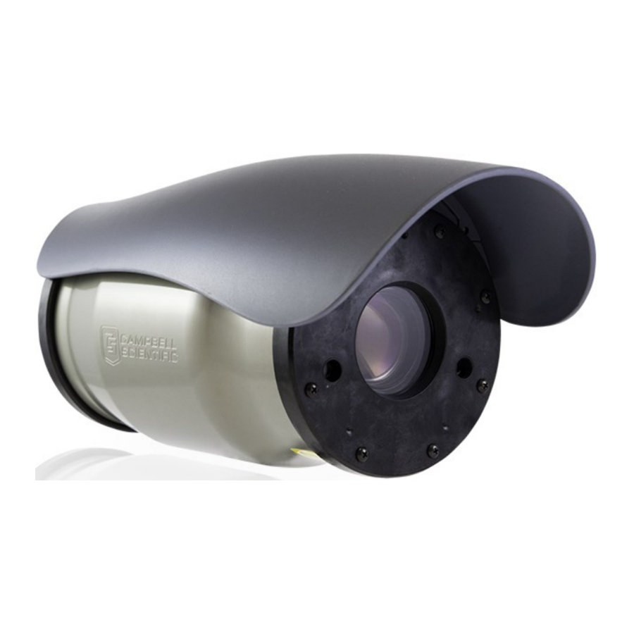
- Page 1 Revision: 08/2021 Copyright © 2016 – 2021 Campbell Scientific, Inc.
- Page 2 IR warning Infrared (IR) is emitted from the CCFC. Do not look directly at the IR LED when the CCFC is connected to power. The CCFC utilizes 2 high intensity nonvisible IR (850 nm) LEDs for night vision illumination. Do not make physical contact with the IR LEDs or place any body part near the IR LEDs (less than 5 cm) while the camera is powered on.
-
Page 3: Table Of Contents
Table of contents 1. Introduction 2. Cautionary statements 3. Initial inspection 4. QuickStart 4.1 Connect to CCFC using Wi-Fi 4.2 Connect your camera using Ethernet cable 4.3 Quick set up to take an image every 15 minutes 5. Specifications 6. Quick notes 6.1 CCFC general... - Page 4 9.2 Power and I/O cable details 9.3 Ethernet cables 10. Using Device Configuration Utility 11. Photo quality 12. NDVI 13. Connecting to the web interface 13.1 Setup using Wi-Fi 13.2 Setup using Ethernet 13.2.1 Link local IP address auto-configuration 14. Camera option using the web interface 14.1 Installing MultiMedia Player 14.1.1 RTSP video stream 14.1.1.1 Sources...
- Page 5 17. Send via PakBus®: PakBus® communications 17.1 Send using PakBus®: concurrent PakBus® communications 17.2 Send via PakBus®: PakBus® graph operations 17.2.1 Data logger settings 17.2.2 Discovery 17.3 Setting up data logger to work with CCFC: PakBus® variable control Table of Contents - iii...
- Page 6 17.3.1 PakBus® control of window defroster function 17.3.2 PakBus® control of CCFC power 17.3.3 Example data logger program – SendVariables instruction 17.3.4 Example data logger program – adding GPS coordinates to the photo banner 17.4 PakBus® neighboring address 18. Power calculations and timings 18.1 Standalone operation...
-
Page 7: Introduction
2. Cautionary statements Although the CCFC is designed to be a rugged and reliable device for field use, care should be taken when handling or moving it to avoid aesthetic damage. Other than the desiccant, there are no user-serviceable parts. Improper disassembly or re- assembly of the device will void the warranty. - Page 8 The CCFC has three stickers on the bottom of the camera: 1. IR Warning Sticker. 2. FCC Information Sticker. 3. Model #, Serial #, and MAC Address Sticker. CCFC Field Camera...
-
Page 9: Initial Inspection
Button indicates the camera has power. Start the computer/mobile device and connect to the camera using its Wi-Fi network. It will appear as CCFC-9999 where 9999 will be the last 4 digits of your camera serial number. CCFC Field Camera... -
Page 10: Connect Your Camera Using Ethernet Cable
CCFC. 4.3 Quick set up to take an image every 15 minutes Do the following to set up the CCFC to take an image every 15 minutes and save the photo to CCFC camera memory. CCFC Field Camera... - Page 11 Table 4-3: Quick set up – taking an image every 15 minutes Step Procedure Connect to Camera using the methods laid out in Connect to CCFC using Wi-Fi (p. 3) or Connect your camera using Ethernet cable (p. 4). Click Create Capture Modes in the Set Up Progress bar at the top.
- Page 12 Type a descriptive title for the lens position, such as fully zoomed or wide view. Slide the Zoom slider to the desired zoom length. The CCFC will auto focus as you change zoom lengths. The CCFC may take a second to respond and display your image in the Live Video feed.
- Page 13 1:07 pm, the photo will be taken at 1:15 pm, then again at 1:30 pm, and so on. For alternate set ups or more information, see Configuration process (p. 11). CCFC Field Camera...
-
Page 14: Specifications
13.0 cm (5.1 in) Width: 13.2 cm (5.2 in) Lens: 4.7 to 84.5 mm, 3 to 55 ° horizontal field of view Photo or video capture triggers: Two independent self timers Motion detect Web page control External trigger CCFC Field Camera... - Page 15 Wi-Fi (supports 802.11bgn in the 2.4 GHz ISM band on channels 1 to 11) Communication protocols: Web interface using web browser Email PakBus® (for Campbell Scientific data loggers) Modem power control Maximum output current: 750 mA at 12 VDC CCFC Field Camera...
-
Page 16: Quick Notes
(photo); avi (video) Size: 16 GB Zoom: 18x optical zoom 6. Quick notes 6.1 CCFC general When ordering the CCFC series, use the model numbers CCFC-RS232 (RS-232 communications (p. 109))or CCFC-RS485 (RS-485 communications (p. 111)). The Setup Button Status LED (Setup Button/Status LED (p. -
Page 17: Campbell Scientific Data Logger Users
6.2 Campbell Scientific data logger users Ensure that the data logger has the latest PakBus® operating system. Use either the CCFC built in-web interface, Device Configuration Utility, or LoggerNet PakBus® Graph to change settings in the camera. Use the Device Configuration Utility to change settings in MD485 or other PakBus®... - Page 18 This table takes into account the camera power settings. It does not include the power draws associated with activating the IR LEDs (refer to IR LED power control (p. 99)) or Lens Defroster Control (p. 101)). CCFC Field Camera...
-
Page 19: Factory Setup
RS-232 communications (p. 109) and RS-485 communications (p. 111). 7. Factory setup Table 7-1 (p. 13) outlines the CCFC factory settings that are relevant for initially communicating with the camera. Table 7-1: CCFC factory default configuration Configuration setting Value Power Mode... -
Page 20: Camera Hardware
Configuration Utility is a free download from the Campbell Scientific website at www.campbellsci.com/downloads . The use of RS-232 serial lines requires the DB9 terminal block adapter (included in the box with the CCFC) to connect to a computer (Factory setup 13)). -
Page 21: Power I/O Connection
Partially On and remain Fully On for a Deep Sleep period of 5 min with the Off Mode Status LED rapidly flashing. Slow Flash Normal Operation in Fully On power 1 sec on, mode. 3 sec off CCFC Field Camera... -
Page 22: Setup Button
(p. 14)) is used to wake the camera from any of the power saving modes. Once the Setup Button is pushed, the CCFC enters a fully powered mode for 5 minutes. During this interval, the camera can be accessed via Ethernet, Wi-Fi, or RS-232/485 to make any necessary configuration changes. -
Page 23: Link To Most Recent Photo And Video
NOTE: The following are examples. The IP address will vary with the camera network configuration. Timed Capture 1: http://1.2.3.4/stc1.jpg http://1.2.3.4/stc1.avi Timed Capture 2: http://1.2.3.4/stc2.jpg http://1.2.3.4/stc2.avi External Trigger: http://1.2.3.4/etc.jpg http://1.2.3.4/etc.avi Motion Detect: http://1.2.3.4/mdc.jpg http://1.2.3.4/mdc.avi CCFC Field Camera... -
Page 24: Ftp Photo Collection From Camera Memory
(p. 73)). However, if you desire to collect a large number of files from an entire folder, using the web interface is cumbersome. Campbell Scientific recommends accessing the CCFC memory using the FTP file transfer process. For most Windows computers, type the IP address assigned to the camera by the network. For example, type ftp://1.2.3.4:21 into a supported web browser, where ‘1.2.3.4’... -
Page 25: Modem Power Control
(p. 62)). 8.5.1 Camera lens and field-of-view The CCFC includes a 4.7 to 84.5 mm lens, which provides approximately a 3-degree horizontal field-of-view when fully zoomed in and a 55-degree horizontal field-of-view when fully zoomed out. The aperture size is F/1.6 to F/2.8. -
Page 26: Temperature Variations And Focus
8.5.4 Lens IR cut filter The CCFC is internally equipped with an IR cut filter. The filter is required to filter out near infrared light that can have an undesirable effect on the photos. The IR filter is also used for NDVI photos. - Page 27 2 of a computer (DTE) DB-9 Connector). Connect to wire RS-232 TX RS-485A when configured to RS-485. Green terminator/connector (Output) Only connect when RS-232 and RS- (FIGURE 9-1 (p. 21)) 485 communications are used for PakBus® or the Device Configuration Utility. CCFC Field Camera...
- Page 28 Connect to external signal source (data logger control terminal). The external signal wakes up or initiates photo/video acquisition. On a Campbell Scientific data logger, connect to a 5 V (5V) or switched 12 V External Trigger Connect to ground if left...
-
Page 29: Power And I/O Cable Details
Ethernet cable with RJ45 connectors to interface the camera. Permanent outdoor and temporary connections in wet or harsh environments require the Environmental Ethernet Cable assembly. Campbell Scientific recommends the use of the environmentally sealed cable at all times when outdoors. -
Page 30: Using Device Configuration Utility
. It is included in installations of LoggerNet, RTDAQ, and PC400. When shipped, the CCFC factory default setting is with the communication lines configured for the RS-232 or RS-485 depending on the model specified at time or order. The following table show wiring for RS-232 communications. - Page 31 2. The Status LED flashes once the camera is powered up (this can typically take 90 seconds), . If the Status LED does not flash, press the Setup button to exit the low powered mode. 3. In the Device Configuration Utility, select the CCFC from the device list and click Connect to connect to the camera.
-
Page 32: Photo Quality
11. Photo quality Lighting conditions have the greatest influence on photo quality. The CCFC camera produces the best photos under normal daylight conditions. Pictures taken in well-lit daylight conditions produce crisper and brighter photos. - Page 33 This can be useful in agriculture for identifying stress in crops, precision farming, and in forestry for quantifying density, or leaf area. The CCFC has a removable IR filter which allows it to capture two images in rapid succession in order to create an NDVI representation image.
- Page 34 + NDVI, this will capture and save two images, one real color image (FIGURE 12-2 (p. 28)) and one NDVI (FIGURE 12-1 (p. 27)). The manual capture feature on the home page for the CCFC also has the NDVI option (Dashboard (p. 39)). FIGURE 12-3. NDVI dropdown CCFC Field Camera...
-
Page 35: Connecting To The Web Interface
The CCFC is Wi-Fi enabled. While the camera is powering up, start the computer/mobile device and connect to the camera using its Wi-Fi network. The camera will appear as CCFC-nnnn (where nnnn is the last four digits of the camera serial number) on the Wi-Fi network. -
Page 36: Camera Option Using The Web Interface
NOTE: To use Link Local, the computer connecting to the CCFC must be configured to use DHCP. If the computer is configured to use a static IP, one of the remaining interface arrangements must be used. 14. Camera option using the... -
Page 37: Sources
14.1.2 UPnP discovery The CCFC supports UPnP for device discovery. Therefore, the CCFC will appear in the Windows Network panel with a name such as CCFC-9999, where 9999 is the actual serial number of the camera. This feature makes it possible to find the camera after connecting it to an existing network using DHCP, regardless of whether the connection is wired via Ethernet or Wi-Fi. -
Page 38: Image Capture Url
14.2 Image capture URL The CCFC is able to preform an image capture and download the image through the browser using a single URL. Use this feature by accessing the URL: http://1.2.3.4/capture.jpg where 1.2.3.4 is the CCFC IP address. There are several parameters that can be configured before preforming the capture. These... - Page 39 NOTE: Once the parameters are set, the camera will save the set parameters for use on the next URL capture while you remain on the CCFC webpage. The parameters return to default after a rest/power down. CCFC Field Camera...
-
Page 40: Web Interface Overview
14.3 Web interface overview Use the web interface to: Fully configure the CCFC View information, system status, date, and time View live video Retrieve photo and video files from the camera memory Access all camera settings Create zoom set points FIGURE 14-1. - Page 41 10 min to ensure the camera memory is not corrupted. Power Icon After the 10 min period, the camera powers up again. In the mobile display, the Power icon appears in the left navigation sidebar. CCFC Field Camera...
- Page 42 You can select a Lens Preset from a drop down and Navigation Live Video adjust the Zoom using a slider. Edit Positions directs Bar – you to the Lens Position option. See Lens Position Mobile 62) for detailed instructions. View CCFC Field Camera...
- Page 43 The homepage of the camera is the Dashboard. There are no operational settings to change on the Dashboard. However, a manual photo capture can be initiated from this page using the Manual Capture button (Dashboard (p. 39)). CCFC Field Camera...
-
Page 44: Live Video Modal
Every web page contains a navigation sidebar on the left with options that allow navigation to the other CCFC web pages. On mobile devices or small screen computers, the sidebar is automatically collapsed to allow more space for content. Reopen the sidebar by clicking the menu key at the top left of the page. -
Page 45: Power Icon
14.3.3 Set Up Progress bar The Set Up Progress bar is visible on every web page. When proceeding through the Set Up Progress workflow to configure the CCFC, the bar is updated with check marks. FIGURE 14-5. Set Up Progress bar The text in this bar is selectable and links to the associated area required to complete setup. - Page 46 FIGURE 14-6. CCFC Dashboard Any web server or FTP activity will reset the sleep timer in the camera, so the camera will stay awake for 5 minutes after the last access to the web page. When a user has the Dashboard open, it constantly accesses the web server as the camera loads the time, temperature, and humidity.
- Page 47 Humidity CCFC internal humidity. Humidity over 50% for an extended period of time is cause for concern. If achieved, contact a Campbell Scientific Support Engineer. Motion CCFC motion detect display. The circle displays as green when motion is detected.
-
Page 48: Capture Modes
Capture Modes allows a user to set how the media event will be captured. The External Trigger and Motion Detect configuration pages include an option labeled Pre- Record In Seconds. By entering a value between 1 and 30 in this field, the CCFC will begin CCFC Field Camera... -
Page 49: Timed Capture
When an event occurs, the CCFC will store the set number of seconds of video to a file and continue recording the live video until the number of seconds has elapsed. Video pre-recording allows the camera to record up to 30 seconds of video leading up to a related capture event. - Page 50 When Timed Capture is enabled, the CCFC uses its internal clock as a trigger to initiate the capture of photos or video. In addition to the primary Timed Capture event, there is also a second independent Timed Capture. Each configuration is independent of the other, but overlapping events may delay or prevent one or the other from occurring.
- Page 51 The camera will not go to sleep in the middle of a photo burst capture. CCFC Field Camera...
- Page 52 Email profiles via the Email Settings modal (Email Send via 87)). Email Drop down to select a configured media profile. Use the Edit button Media Profile to setup Media profiles via the Media Settings modal (Media Settings (p. 65)). CCFC Field Camera...
- Page 53 Schedule video capture by entering a value in minutes in Take Photo Every. Minimum allowable value is 1, maximum is 1440. Input what Scheduled time the capture event occurs between using the start and end time values. CCFC Field Camera...
- Page 54 YY/MM folder exceeds 1000. Toggle Enable to initiate sending videos via email. Send via Drop down to select a configured email settings profile. Use the Edit Email Destination button to setup Email profiles via the Email Settings modal (Email 87)). CCFC Field Camera...
-
Page 55: External Trigger
(p. 21) for information on which wires need to be connected. FIGURE 14-10. External Trigger External Trigger can be configured to Active High or Active Low. When set to Active High, 0 volts is the Inactive state and a positive voltage is the Active state. CCFC Field Camera... - Page 56 The CCFC is shipped from the factory with a pull down resistor connected to the External Trigger and the External Trigger set to Active High. With this default setting, when no signal is applied to the input, the External Trigger is inactive. A positive voltage is required to change to the active state.
- Page 57 The camera will not go to sleep in the middle of a photo burst capture. CCFC Field Camera...
- Page 58 Email profiles via the Email Settings modal (Email Send via 87)). Email Drop down to select a configured media profile. Use the Edit button Media Profile to setup Media profiles via the Media Settings modal (Media Settings (p. 65)). CCFC Field Camera...
- Page 59 Text a directory name in the File Explorer (see File explorer (p. 73)). Active High Configures External Trigger to capture on a positive voltage. External Trigger Active Low Configures the External Trigger to capture with 0 volts. CCFC Field Camera...
- Page 60 (Email 87)). Toggle Enable to initiate sending videos via FTP. Send via Drop down to select a configured FTP profile. Use the Edit button to Destination setup FTP profiles via the FTP Settings modal (FTP (p. 85)). CCFC Field Camera...
-
Page 61: Motion Detect
20 second moving average of the scene. For example, if a CCFC was focused on a ceiling fan that was off, the CCFC motion detect would be triggered if the fan was turned on. After a period of 20 seconds the motion detect would no longer be triggered... - Page 62 A value of 1 is the least sensitive motion detect threshold setting and a value of 99 is the most sensitive motion detect threshold setting. Motion detect can be a complicated feature to implement. Campbell Scientific recommends initially setting the motion detect threshold to 50 and adjust it to get the best setting for the application.
- Page 63 The delay from motion occurring to photo capture is typically 1 second (10 seconds for a 5MP photo). Motion detect is disabled when the light level is too low, or when the IR LEDs are active. FIGURE 14-14. Motion Detect: Create New Profile CCFC Field Camera...
- Page 64 The camera will not go to sleep in the middle of a photo burst capture. CCFC Field Camera...
- Page 65 Email profiles via the Email Settings modal (Email Send via 87)). Email Drop down to select a configured media profile. Use the Edit button Media Profile to setup Media profiles via the Media Settings modal (Media Settings (p. 65)). CCFC Field Camera...
- Page 66 A Value of 99 is the most sensitive and is most susceptible to false triggers. Sensitivity 1 to 99 NOTE: A larger range of sensitivity (-99999 to +99999) can be used when the standard range of 1-99 does not suit requirements. CCFC Field Camera...
- Page 67 Options Reducing the number of files in a folder speeds up the storing and file management process. Speed advantages are only noticeable if the number of files in the YY/MM folder exceeds 1000. CCFC Field Camera...
-
Page 68: Lens Position
These positions are saved to the camera memory to optimize media capture events. If no lens position is set for the event, the camera will continue to use the current position. FIGURE 14-15. Lens Position CCFC Field Camera... - Page 69 Opens Live Video to view and edit current lens position. Title Text Name the lens position in order to navigate to it at a later date. Zoom Slider Zooms the camera lens in and out (close-up to wide angle). CCFC Field Camera...
- Page 70 Saves Lens Position. Settings To ensure a clear photo, please refer to Table 14-12 (p. 64) referring to the zoom level and minimum focal distance. Table 14-12: Minimum focal distance Minimum focal distance Zoom position (centimeters) 1000 CCFC Field Camera...
-
Page 71: Media Settings
FIGURE 14-18. Media Settings 14.7.1 Photo Capture The Photo Capture settings are significant in determining how the camera will operate. The description of the parameters for the Photo Capture setup are outlined in Table 14-13 (p. 66). CCFC Field Camera... - Page 72 Opens Media Settings: Edit Photo Profile to add parameters. Name the setting in order to navigate to it at a later date. This title Title Text will appear in the drop down when setting up a Capture Modes (Capture modes (p. 42)). CCFC Field Camera...
- Page 73 2592 X 1944 + NDVI NDVI (NDVI (p. 26)) Lossless Very High Quality High Medium Low Text Title None File Name Date and Time Convention Drop down Numerical Increment (from 1+). Enter the number to start the increment from. CCFC Field Camera...
- Page 74 Text to be displayed on the photo. (e.g. site location information). Text Character limits in Table 14-14 (p. 69) are based on photo resolution. Enable or Disable Serial and Serial: serial number of the camera. Temperature Temperature: internal temperature of the camera. CCFC Field Camera...
- Page 75 320 x 192 High Medium Lossless Very High 320 x 240 320 x 256 High Medium Lossless Very High 640 x 352 640 x 384 High Medium Lossless Very High 640 x 480 640 x 512 High Medium CCFC Field Camera...
-
Page 76: Video Capture
Actual file size varies based on lighting conditions and subject matter 14.7.2 Video capture By selecting Video Capture, the Media Setting: Edit Video Profile web page appears. There are two subtabs that provide two independent types of video to be recorded. CCFC Field Camera... - Page 77 720p 30FPS video, which is 500 KB (0.5 MB) per second of video. The smallest video files are produced by the 320 x 240 7.5 FPS video, which is 9 KB per second of video. FIGURE 14-21. Media Settings: Edit Video Profile FIGURE 14-22. Video Settings Modal CCFC Field Camera...
- Page 78 Enable File YYYY/MM/DD/HH/MM/SS Time Caption MM/DD/YYYY/HH/MM/SS Stamp MM/DD/YYYY/HH/MM MM/DD/YYYY Text to be displayed on the video. (e.g. site location information). Text Character limits for video are visible in Table 14-16 (p. 73) and are based on resolution. CCFC Field Camera...
-
Page 79: File Explorer
This page shows the actual space available for each capture event, as well as the space currently being used. CCFC Field Camera... - Page 80 The camera creates subfolders that are named by date. The date subfolders can be configured to store photos in folders named either by Year_Month or Year_Month_Day. NOTE: Video files cannot be downloaded from the File Explorer in iOS mobile devices, as per Apple regulations. CCFC Field Camera...
-
Page 81: Settings
14.9 Settings 14.9.1 General Settings The General Settings page has three configuration sections: Camera Name Date and Time Settings Default Factory Reset FIGURE 14-25. General Settings CCFC Field Camera... - Page 82 Sync with SNTP Server: a means of synchronizing the CCFC onboard and Time clock with a specified SNTP server to ensure the CCFC clock is always Date and accurate. A time zone offset can be configured for the CCFC. See SNTP (p.
-
Page 83: Sntp
The configuration of an SNTP server provides a means of synchronizing the onboard clock of the CCFC with the specified SNTP server. This ensures that the camera clock is always accurate. You can also configure a time zone offset for the camera. -
Page 84: Ethernet Settings
FIGURE 14-28. Network Pop-up on Google Chrome 14.9.2.1 Ethernet Settings The CCFC default is to use the static IP address 1.2.3.4. As required, the CCFC can be configured for a DHCP Network. The available network settings are displayed on the Ethernet Settings page. - Page 85 Only set if DHCP is Disabled. Obtain Primary Name Server 192.168.1.1 Server from a network administrator. 80 or values Alternate ports can be used for the http interface. Obtain HTTP Port between 1025 and HTTP Port from a network administrator. 65535 CCFC Field Camera...
-
Page 86: Wi-Fi Settings
The Wi-Fi on the camera can connect to an existing network or become a Wi-Fi access point. By default, the camera Wi-Fi is set up as an access point with the name CCFC-9999, where 9999 is the serial number of the camera. This allows the user to quickly find and connect to the camera on the first power up. -
Page 87: Wi-Fi Access Mode
By default, the camera is accessible at http://10.0.0.1 when connecting to the Wi-Fi Access Point. There are seven Access Point settings for the Wi-Fi AP mode. The first four should be configured for all installations. Only change the last three if there is a specific reason (Table 14-20 (p. 82)). CCFC Field Camera... - Page 88 Number (e.g. 255.0.0.0) Network mask of the Wi-Fi network to be used. DHCP Start Number (e.g. 10.0.0.10) Start of the address range to give to connecting clients. DHCP End Number (e.g. 10.0.0.19) End of the address range to give to connecting clients. CCFC Field Camera...
-
Page 89: Existing Network
FIGURE 14-32. Connect to existing network The Scan For Networks button appears when the Access Mode is in Existing Network. This button searches for nearby Wi-Fi access points and displays a list. The list includes the name, address, CCFC Field Camera... - Page 90 IP Address custom configurations. Netmask The network mask to use when connecting to the Wi-Fi network. Default Gateway The network gateway to use for Internet traffic. Primary Name Saver The DNS server to use for address resolution. CCFC Field Camera...
-
Page 91: Status Settings
This section is only necessary when using an external server to store media files. File Transfer Protocol (FTP) allows media files to be stored on a third-party server. The CCFC allows for two external servers for media storage to be set up. - Page 92 If an FTP transfer failure, the CCFC resends the file to the FTP server for up to two times before aborting the file transfer.
-
Page 93: Email
Encrypted connections are more secure. In the event of a SMTP transfer failure, the CCFC retries sending the file to the mail server up to two times before aborting the file transfer. - Page 94 Enable when email server requires authentication. If Enabled, an Requires Drop down Account and Password are required. Disabled is the default Authentication setting. Sender (From) The email address associated with the account is normally used Text Address here. The CCFC cannot receive emails. CCFC Field Camera...
-
Page 95: Pakbus
14.9.3.3 PakBus® PakBus® is used to enable media files to be sent to a PakBus® compatible device (Campbell Scientific data loggers). Ensure the PakBus® device is set up to receive (see LoggerNet Manual, which is available for download at www.campbellsci.com/loggernet... - Page 96 Communications using the PakBus® protocol enables remote retrieval and/or storage of photos or video to external devices such as compatible Campbell Scientific data loggers. Meaning, photos can be stored on the data logger, which allows for remote retrieval using the data logger’s communication device.
- Page 97 PakBus® the CCFC PakBus® communication lines. This allows the 0 to 4095 Neighbour neighbor to relay communication between the CCFC and the final destination for the data. 0 is autodetect. Communication Extra delays may be required for certain communication links...
-
Page 98: Camera Operation
Deep Sleep State: provides very good power savings. Recommended for use if more than 24 triggers are expected per day. Off State: offers the best power savings. Useful if less than 24 images or video captures are required per day. CCFC Field Camera... - Page 99 @ 12 VDC. The Ethernet is normally turned off and is only Full Power Save enabled when outgoing communications are required (email or FTP). User pushes the Setup Button to temporarily enable the Ethernet port for web page access. CCFC Field Camera...
- Page 100 Full Power Save Mode required (email or FTP). User pushes the Setup Button to temporarily enable the Ethernet port for web page access. The camera can respond to RS-232 or RS-485 communication in this mode. CCFC Field Camera...
- Page 101 If Ethernet communications are not used, this can reduce the power consumption of the camera by 50 mA when the camera exits the Deep Sleep State. NOTE: Ethernet Power Mode (p. 96) for other settings that influence power consumption. CCFC Field Camera...
-
Page 102: Ethernet Power Mode
Ethernet Power Mode dictates the Ethernet power draw. To reduce power consumption, the CCFC includes the ability to control the power characteristics of the Ethernet port. The specific behavior of the camera Ethernet power save is also influenced by the Power Mode of the camera. -
Page 103: Wi-Fi Power Mode
Wi-Fi will only power up to transmit files after a capture event. A button press enables the Wi-Fi for 5 min. Power Save Attaching the external trigger wire (blue) to a power source (>2.5 VDC, maximum Mode 30 VDC) turns the Wi-Fi on until power is removed. CCFC Field Camera... -
Page 104: Night Mode
Infrared LEDs in order to capture photos in complete darkness. IR illumination can be turned on or off to suit low light needs. The CCFC has an integrated IR filter that automatically switches in and out to suit the lighting conditions. This optimizes photo quality in low light and daytime light. -
Page 105: Ir Led Power Control
Filter control Outdoor photos contain a great deal of IR light from the sun. The photo sensor in the CCFC is sensitive to this IR light and will pick it up causing the photo to look improperly colored. The lens on the CCFC is equipped with a switchable IR filter to counteract this effect. -
Page 106: Light Power Control
FIGURE 14-44. Digital I/O Settings Modem Power Control The Modem Power Control setting controls the yellow Power I/O signal line of the CCFC camera. The yellow wire, or switch output, is intended to manage the power to a communication device such as a cell modem. -
Page 107: Lens Defroster Control
This option enables the CCFC to supply up to a maximum of 750 mA of current. The voltage level will be the same as the camera input power (12 VDC). Some modems require a warm-up time or a period of time to register on a network. The Early Power On option is there for this purpose. -
Page 108: Advanced
(p. 113) for details on controlling the defroster from your connected data logger 14.9.5 Advanced 14.9.5.1 GPS Coordinates Photos created by the CCFC can be geotagged, that is GPS coordinates can be embedded in the photo files metadata. CCFC Field Camera... - Page 109 West) must be selected from the drop down and numerical values for degrees, minutes, and seconds must be entered. FIGURE 14-49. GPS: Degrees, Minutes, Seconds When Decimal Degrees is selected, Latitude (-90.0000 to 90.0000) and Longitude (-180.0000 to 180.0000) values are entered. CCFC Field Camera...
-
Page 110: Import/Export
Use the Import/Export tool to maintain continuity between cameras. It can import and export settings to and from the CCFC camera. Additionally, Import/Export allows for configuration settings to be uploaded or downloaded via the web interface. The .xml configuration files are also compatible with Device Configuration Utility. - Page 111 Variable Options Description Uploads selected file from the computer. This file can be found on Choose file the Campbell Scientific website www.campbellsci.com/ccfc If selected, it updates IP address information from the file. Update IP address Not selecting this will not update the IP address information. This is...
-
Page 112: Update
14.9.5.3 Update Use Update to update the firmware in the camera. It is recommended that you regularly check for firmware updates on the Campbell Scientific website www.campbellsci.com/ccfc to ensure that the camera has the most recent version of firmware. FIGURE 14-52. Update Once a file is downloaded, click on the Browse button to select the new firmware update with the tar.gz file extension. -
Page 113: Users
Without this activated, the camera is open to the Internet. A total of 10 users can be added to the CCFC. By default, cameras are shipped with the security authentication disabled. When Authentication is set to Enable, users will be prompted for a User Name and Password before access is given. -
Page 114: History
Other types of event messages and log files include: Notification that the camera memory or allocated memory is full when using fill and stop memory management. Communication and file transfer errors that include: Email PakBus® CCFC Field Camera... -
Page 115: Communications
This value is displayed on the web interface under Settings > File Transfer > PakBus®. FIGURE 15-1. PakBus® settings The CCFC Power I/O port configuration defaults to a 3-wire RS-232 connection (Tx, Rx, G), as well as power. The wires connect directly to the control terminals of a compatible data logger. For... - Page 116 9-pin serial port. The adapter is included with the CCFC. FIGURE 15-2. DB9 FEMALE to Terminal Block Adapter Table 15-1: CCFC connections to RS-232 port Wire color Function Connection required...
-
Page 117: Communications
17. Send via PakBus®: PakBus® communications The CCFC camera uses the PakBus® protocol to send photo or video files from the camera to a Campbell Scientific data logger or other PakBus® compatible device. The LoggerNet Tool PakBus® Graph can be used to change the configuration of a camera. PakBus® Graph is discussed in Send via PakBus®: PakBus®... -
Page 118: Send Using Pakbus®: Concurrent Pakbus® Communications
The CCFC may produce video files that exceed 30 MB. Sending such a large file to a data logger using PakBus® can be problematic. For this reason, the CCFC does not send files using PakBus® that are larger than 2 MB. The camera is a PakBus® leaf node and is not capable of performing routing. However, the CCFC can communicate with devices several hops away on the PakBus®... -
Page 119: Setting Up Data Logger To Work With Ccfc: Pakbus® Variable Control
17.3 Setting up data logger to work with CCFC: PakBus® variable control The camera can receive variables, commands, or text from a data logger. The specific operational parameters that can be altered or controlled include: File Captions Camera Window Defroster... -
Page 120: Pakbus® Control Of Window Defroster Function
The defroster will not be allowed to turn on at internal temperatures above 25 °C. 17.3.2 PakBus® control of CCFC power A PakBus® command can safely shut the CCFC down. Write 1 (or any nonzero value) to the public Boolean variable CCFCShutdown and the camera will safely power down. The shutdown process can take up to 30 seconds. -
Page 121: Example Data Logger Program - Adding Gps Coordinates To The Photo Banner
Type the address of the PakBus® device connected to the CCFC PakBus® communication lines and the neighbor device will relay communications between the CCFC and the final destination for data. Set the PakBus® address to zero (0) if the CCFC is directly connected to the final destination. -
Page 122: Standalone Operation
Full Power Save 200 mA 6 mA 0.15 0.18 0.53 Mode 25 Sec/JPG 250 mA Always On 1 mA 0.041 0.22 120 Sec/JPG Off State Full Power Save 200 mA 1 mA 0.037 0.18 1.93 Mode 120 Sec/JPG CCFC Field Camera... -
Page 123: Operation With Communications
60 seconds 38400 0.0054 Ah 40 seconds 57600 0.0044 Ah 30 seconds 115200 0.0038 Ah To estimate the system power consumption, use Table 18-2 (p. 117) along with the communication times to calculate the power consumption as follows: CCFC Field Camera... -
Page 124: Ccfc Compatibility
Total power = quiescent power + active power The total power consumption for the example is: Total power = 0.1418 Ah/day + 0.0917 Ah/day Total power = 0.2335 Ah/day 19. CCFC compatibility The following table lists compatible contemporary and retired Campbell Scientific data loggers. CCFC Field Camera... -
Page 125: Campbell Scientific Data Logger Interface Guide
Cables/wiring (p. 20) for wiring details. The CCFC RS-485 interface can also be used. Only the CR1000X and CR6-series data loggers have a built-in RS-485 interface. Other data loggers require the use of an MD485 interface to provide conversion of the RS-485 signal (see RS-485 communications (p. -
Page 126: Data Logger Files Manager
Optional data logger keypad and display NOTE: The CCFC will not send any files using PakBus® that are greater than 2 MB. 20.2 Data logger files manager The Files Manager setting on the data logger facilitates the management of jpeg and avi files that are received from the camera. -
Page 127: Data Logger Com Port (Control Port) Communications
Adjust the RS-485 settings if files transfer over RS-485 extremely slowly or if a file is larger than~20 K 1. Access the Device Configuration Utility software 2. Select your data logger, the control port, and click Connect CCFC Field Camera... -
Page 128: Remote Photo Retrieval
The CCFC web interface also has permanent links for downloading the most recently captured photos or video files saved to the camera memory (see Image capture URL (p. -
Page 129: Using Loggernet File Control
Connect Screen > File Control allows photos or video stored in the data logger memory to be viewed or collected on demand. It can also be used for debugging the CCFC. File Control requires a communications connection to the data logger. - Page 130 (compact flash module). The devices are listed in the left side of the File Control panel. To view a device files, click the device listed in the panel (FIGURE 21-3 (p. 124)). Click Retrieve to download the photo or video from the data logger. FIGURE 21-3. USR drive view in File Control CCFC Field Camera...
-
Page 131: Mounting
All that is required is an appropriate mounting fixture. CAUTION: The enclosure is not intended for operation under water. FIGURE 22-1. CCFC mounting kit The camera has three ¼-20 threaded mounting holes (see FIGURE 22-2 (p. - Page 132 Do the following to use the optional mounting kit to secure the camera to a crossarm or 1.5 in outer diameter pipe: 1. Align the outer holes of the CCFC with the mounting bracket center hole and 180 ° slot. 2. Place a washer and ¼-20 x 0.5-inch Hex bolt in the center hole and 180 ° slot and loosely tighten.
-
Page 133: Maintenance
23. Maintenance The CCFC requires little maintenance. Keeping the camera lens window clean is important for the longevity of the camera and photo and video quality. 23.1 Lithium battery The camera is equipped with a lithium thionyl chloride battery. The battery maintains the clock functionality for periods when power is not connected to the camera. -
Page 134: Ndvi
24.3 NDVI NDVI functions only during daylight hours. CCFC Field Camera... -
Page 135: Appendix A. Ccfc Camera Accessories
A.1 CCFCCBL1-L power and I/O cable The CCFCCBL1-L power and I/O cable supplies power and serial communications to the CCFC. This cable can also provide power to an external communication device or trigger the CCFC to initiate photo or video capture. -
Page 136: Ccfccbl3-L Environmental Ethernet Cable
RoHS compliant FIGURE A-2. CCFCCBL3-L environmental Ethernet cable As of early 2018, all CCFC cameras are manufactured with a new environmental Ethernet connector. This new connector is easier to use and provides improved ruggedness and sealing. CCFCs with a serial number of 1277 or greater will be manufactured with the new Ethernet connector, which requires the mating cable, model number CCFCCBL3-L. - Page 137 FIGURE A-3. Backplate – new FIGURE A-4. Backplate – old CCFC Field Camera...
- Page 138 FIGURE A-5. CCFCCBL3-L Ethernet connector – new FIGURE A-6. CCFCCBL2-L Ethernet connector – old CCFC Field Camera...
-
Page 139: 18549 Mounting Kit
A.3 18549 mounting kit Details: Mounting kit with U-bolt and fasteners FIGURE A-7. 18549 Mounting Kit The 18549 mounts to a pipe with a maximum outer diameter of 1.5-inch. CCFC Field Camera... -
Page 140: 28840 Db9 Female To Terminal Block Adapter
A.4 28840 DB9 female to terminal block adapter Details: DB9 FEMALE to terminal block interface with hood and hardware kit FIGURE A-8. 28840 DB9 FEMALE To Terminal Block Adapter CCFC Field Camera... - Page 141 See Product Details on the Ordering Information pages at www.campbellsci.com . Other manufacturer's products, that are resold by Campbell Scientific, are warranted only to the limits extended by the original manufacturer. Refer to www.campbellsci.com/terms#warranty for more information.
- Page 142 To obtain a Returned Materials Authorization or Repair Reference number, contact your CAMPBELL SCIENTIFIC regional office. Please write the issued number clearly on the outside of the shipping container and ship as directed. For all returns, the customer must provide a “Statement of Product Cleanliness and Decontamination”...
- Page 143 Do not recharge, disassemble, heat above 100 °C (212 °F), solder directly to the cell, incinerate, or expose contents to water. Dispose of spent batteries properly. WHILE EVERY ATTEMPT IS MADE TO EMBODY THE HIGHEST DEGREE OF SAFETY IN ALL CAMPBELL SCIENTIFIC PRODUCTS, THE CUSTOMER ASSUMES ALL RISK FROM ANY INJURY RESULTING FROM IMPROPER INSTALLATION, USE, OR MAINTENANCE OF TRIPODS, TOWERS, OR...
- Page 144 Campbell Scientific Regional Offices Australia France Thailand Location: Garbutt, QLD Australia Location: Vincennes, France Location: Bangkok, Thailand Phone: 61.7.4401.7700 Phone: 0033.0.1.56.45.15.20 Phone: 66.2.719.3399 Email: info@campbellsci.com.au Email: info@campbellsci.fr Email: info@campbellsci.asia Website: www.campbellsci.com.au Website: www.campbellsci.fr Website: www.campbellsci.asia Brazil Germany Location: São Paulo, SP Brazil...
Need help?
Do you have a question about the CCFC and is the answer not in the manual?
Questions and answers