Advertisement
GENERAL TROUBLESHOOTING
This guide is intended to provide basic functional diagnostics and will assist in determining
the source of the problem. Choose Power Fault or Actuator Fault and follow the steps.
Are any lights on the Digital Switch illuminated?
NO LIGHTS
POWER FAULT
If you have no lights,
proceed to
"System Inoperative"
SYSTEM INOPERATIVE (Power Fault)
Step 1:
Operate the system in TEST MODE.
TEST MODE
Step 1:
Press and hold all four keypad buttons down for approximately
three seconds. The LEDs on the keypad should track down than back up
and stop with the top triangular LED lit on each side.
Step 2:
Press the left side button on the keypad labeled "DOWN". The
starboard actuator should extend and the left side indicating lights should
track.
Step 3:
Press the right side button on the keypad labeled "UP". The port
actuator should extend and the right side indicating lights should track.
Step 4:
Momentarily press all four keypad buttons down simultaneously.
Both actuators should retract fully and keypad should have no indicating
lights on.
• If the system works in the Test Mode there is a problem with the accessory signal.
Check for proper connection to the orange accessory wire of the control box.
NOTE:Under normal operation the control box's orange accessory wire requires a 12V level
or a tachometer signal to turn the control box ON (top triangular LEDs on switch are lit)
• If the system does not work in Test Mode continue to Step 2.
Step 2:
Verify there is 12V or 24V at the Power Plug: Disconnect the Power Plug from the control box's power
receptacle
and measure voltage using a DC voltmeter.
• If 12V or 24V is not at the Power Plug across the two pins,
step 1: Check the fuse or circuit breaker (between
battery and control box)
step 2:
Verify that the power connection is firmly
attached and that 12 or 24 volts is available.
step 3:
Verify the Orange wire is connected to a 12
or 24V source or an Engine Tach Signal.
step 4: Check battery switch.
• If 12V or 24V is at the Power Plug across the two pins,
Check the key pad connection.
Step 3:
Call Lenco Marine for further technical assistance.
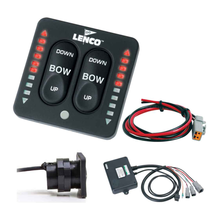
Lenco actuators come with 6FT actuator cables that feature Deutsch terminations.
Boat builders may use a separate wire harness connecting power and actuators to control box.
If you're not certain if there is a separate connection in your boat, contact the boat manufacturer.
FOR ADDITIONAL INFORMATION, CONTACT LENCO'S TECHNICAL SERVICE DEPARTMENT AT:
TEL: 772-288-2662
FAX:772-288-2566
FOR 123SC TRIM TAB SYSTEM
LIGHTS
PORT SIDE FAULT
STBD SIDE FAULT
If you have any of these readings,
proceed (on the next page)to
EMAIL: INFO@LENCOMARINE.COM
BOTH SIDE FAULT
If you have this reading
and are still experiencing
a problem, call Lenco.
1
20 Amp Fuse
2
Orange Wire Connection
Key Pad
Connection
PG 1
LIGHTS
GOOD READING
Press &
Hold 3 Sec.
Triangular
LEDs Should
Be Illuminated
3
Power Wire Connection
4
Battery switch
(images would vary)
11.08.08
Advertisement
Table of Contents

Summary of Contents for LENCO 123SC
- Page 1 Step 3: Call Lenco Marine for further technical assistance. Lenco actuators come with 6FT actuator cables that feature Deutsch terminations. Boat builders may use a separate wire harness connecting power and actuators to control box. If you’re not certain if there is a separate connection in your boat, contact the boat manufacturer.
- Page 2 Proceed to Step 7. Step 7: Attach the port and starboard connectors to the system. If the fault reading continues, contact Lenco’s Customer Service at: info@lencomarine.com or 772-288-2662 FOR ADDITIONAL INFORMATION, CONTACT LENCO’S TECHNICAL SERVICE DEPARTMENT AT: TEL: 772-288-2662 FAX:772-288-2566 EMAIL: INFO@LENCOMARINE.COM 11.08.08...
Need help?
Do you have a question about the 123SC and is the answer not in the manual?
Questions and answers