
Summary of Contents for Sfar SFAR-1M-4DI
- Page 1 SFAR-1M-4DI User Manual Expansion Module – 4 Digital Inputs Global Control 5 Sp. z o.o. Warsaw, Poland www.gc5.pl Version 3.0 Page 1 / 12...
-
Page 2: Table Of Contents
SFAR-1M-4DI User Manual Table of contents 2.1. Purpose and description of the module ............... 4 2.2. Technical specifications ....................5 2.3. Dimensions of the product ..................... 6 3.1. Grounding and shielding ....................6 3.2. Network termination ......................7 3.3. Types of Modbus registers ..................... 7 3.4. - Page 3 SFAR-1M-4DI User Manual Thank you for choosing our product. This manual will help you with proper handling and operating of the device. The information included in this manual have been prepared with utmost care by our professionals and serve as a description of the product without incurring any liability for the purposes of commercial law.
-
Page 4: Purpose And Description Of The Module
SFAR-1M-4DI User Manual Safety rules 1. Refer to this manual before the first use 2. Make sure that all cables are connected properly before the first use 3. Please ensure proper working conditions, according to the device specifications (e.g., supply voltage, temperature, maximum power consumption) 4. -
Page 5: Technical Specifications
SFAR-1M-4DI User Manual 2.2. Technical specifications Voltage 10-38 V DC; 10-28 V AC Power Supply 1 W @ 24 V DC Power consumption 2 VA @ 24 V AC No of inputs Voltage range 0 – 36 V Low State „0”... -
Page 6: Dimensions Of The Product
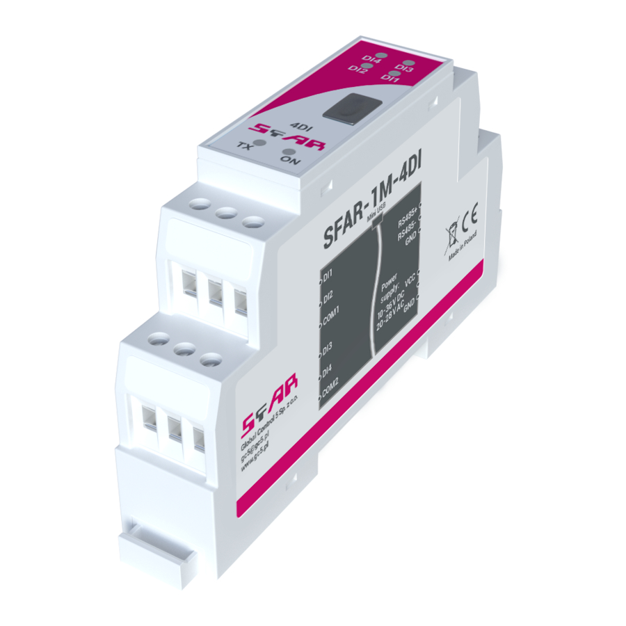
SFAR-1M-4DI User Manual 2.3. Dimensions of the product The appearance and dimensions of the module are shown below. The module is mounted directly to the rail in the DIN industry standard. Picture 1 - Dimensions of the product Configurating of the communication 3.1. -
Page 7: Network Termination
SFAR-1M-4DI User Manual 3.2. Network termination Transmission line effects often represent the problem of data communication networks. These problems include reflections and signal attenuation. To eliminate the presence of reflections at the end of the cable, the cable must be terminated at both ends with a resistor across the line equal to its characteristic impedance. -
Page 8: Configuration Registers
SFAR-1M-4DI User Manual 3.4.2. Configuration registers Modbus Name Values Address 0 – 2400 1 – 4800 2 – 9600 3 – 19200 40003 0x02 Baud rate 4 – 38400 5 – 57600 6 – 115200 other – value * 10 0 –... -
Page 9: Block Diagram
SFAR-1M-4DI User Manual Indicator Description LED indicates that the module is correctly powered. The LED lights up when the unit received the correct packet and sends the answer. 1, 2, 3, 4 LED indicates that on the input is high state. -
Page 10: Registered Access
SFAR-1M-4DI User Manual Modules Registers 6.1. Registered access Modbus Dec Hex Register Name Access Description 30001 0x00 Version/Type Read Version and Type of the device 30002 0x01 Address Read Module Address 40003 0x02 Baud rate Read & Write RS485 baud rate... -
Page 11: Bit Access
SFAR-1M-4DI User Manual Modbus Dec Hex Register Name Access Description 40067 66 0x42 CCounter 4 MSB Read & Write 32-bit value of captured counter 4 40068 67 0x43 CCounter 4 LSB Read & Write 40069 68 0x44 Counter Config 1 Read &... - Page 12 SFAR-1M-4DI User Manual Configuration software Modbus Configurator is the type of software which is designed to set the communication module registers over Modbus network as well as to read and write the current value of other registers of the module. It’s a convenient way to test the system as well as to observe real- time changes in the registers.
Need help?
Do you have a question about the SFAR-1M-4DI and is the answer not in the manual?
Questions and answers