
Related Manuals for Honda Power Products WJR1525

Summary of Contents for Honda Power Products WJR1525
- Page 1 POWER SPRAYER WJR1525•WJR2525 OWNER'S MANUAL MANUEL DE L'UTILISATEUR BEDIENUNGSANLEITUNG MANUAL DE EXPLICACIONES...
- Page 2 Honda WJR1525·2525 OWNER’S MANUAL Original instructions MANUEL DE L’UTILISATEUR Notice originale BEDIENUNGSANLEITUNG Originalbetriebsanleitung MANUAL DE EXPLICACIONES Manual original The “e-SPEC” mark symbolizes environmentally responsible technologies applied to Honda power equipment, which contains our wish to “preserve nature for generations to come.”...
- Page 3 Thank you for purchasing a Honda power sprayer. This manual covers the operation and maintenance of Honda power sprayer WJR1525/WJR2525. All information in this publication is based on the latest product information available at the time of approval for printing.
- Page 4 Disposal To protect the environment, do not dispose of this product, battery, engine oil, etc. carelessly by leaving them in the waste. Observe the local laws and regulations or consult your authorized Honda dealer for disposal.
-
Page 5: Table Of Contents
CONTENTS 1. SAFETY INSTRUCTION ............... 3 2. SAFETY LABEL LOCATIONS............. 13 CE mark location ................. 15 3. COMPONENT IDENTIFICATION ............16 4. PRE-OPERATION FOR STARTING ........... 17 5. STARTING THE ENGINE..............25 • High altitude operation ..............28 6. STOPPING THE ENGINE ..............29 7. -
Page 6: Safety Instruction
1. SAFETY INSTRUCTION 1. Field of application The device is approval for agricultural use. Other possible fields of application: forestry, hops cultivation, fruit growing, specialized cultivation, viticulture, tree nurseries, vegetable farming, non-cropland, grassland, storage protection, greenhouse cultivation, cultivation of ornamentals. 2. - Page 7 4. Information about how long the sprayer can be used. • The same person should not perform spray operations for a long time or every day. • Do the operations while taking a moderate rest. 5. Information about the device operating and setting ranges. The following must be entered individually for each nozzle assembly.
- Page 8 To ensure safe operation Operator Responsibility • Any part from the machine is a potential source of danger if the machine is used in abnormal conditions or if the maintenance is not done correctly. • Read the owner’s manual carefully. Be familiar with the controls and their proper use of the power sprayer.
- Page 9 To ensure safe operation Operator Responsibility • Never operate the power sprayer while: — people, especially children or pets are nearby. — user is fatigued or under medication, or has swallowed substances known to affect judgement or reactions. • Keep in mind that the operator or user is responsible for accidents or hazards occurring to other people or their property.
- Page 10 To ensure safe operation How to handle agricultural chemicals When handling agricultural chemicals, follow the directions of the manufac- turer or distributor. Also, follow the laws and regulations. • The people that spray agricultural chemicals, or who assist in spraying them, must put on protective clothes so they don’t inhale the chemicals or touch them directly.
- Page 11 To ensure safe operation How to handle agricultural chemicals • Before starting the engine, make sure that the sprayer hose is securely installed into the power sprayer, and that the nozzle lever is in the “CLOSED” position. If you fail to do so, agricultural chemicals may splash on you during operation.
- Page 12 To ensure safe operation How to handle agricultural chemicals • Do not spray the chemicals in the daytime while the temperature is high, or on a day of strong wind. Do not spray the chemicals in a busy place during a busy time especially when school children are likely to pass through.
- Page 13 To ensure safe operation How to handle agricultural chemicals • After using the power sprayer, store it in a place where children and domestic animals are locked out. Careless storage can cause exposure to children or animals, which could be harmful to their health. •...
- Page 14 To ensure safe operation Fire and Burn Hazard Gasoline is extremely flammable, and gasoline vapor can explode. Use extreme care when handling gasoline. Keep gasoline out of reach of children. • Store fuel in containers specifically designed for this purpose. •...
- Page 15 To ensure safe operation Carbon Monoxide Poisoning Hazard Exhaust contains poisonous carbon monoxide, a colorless and odorless gas. Breathing exhaust can cause loss of consciousness and may lead to death. • If you run the engine in an area that is confined or even partially enclosed, the air you breathe could contain a dangerous amount of exhaust gas.
-
Page 16: Safety Label Locations
2. SAFETY LABEL LOCATIONS These labels warn you of potential hazards that can cause serious injury. Read the labels and safety notes and precautions described in this manual carefully. If a label comes off or becomes hard to read, contact your Honda dealer for a replacement. - Page 17 • Honda power sprayer is designed to give safe and dependable service if operated according to instructions. Read and understand the Owner’s Manual before operating the power sprayer. Failure to do so could result in personal injury or equipment damage. •...
-
Page 18: Ce Mark Location
CE mark location Sales agency address Manufacturer and address Year of manufacture Machine mass (When a chemical tank is full) Model... -
Page 19: Component Identification
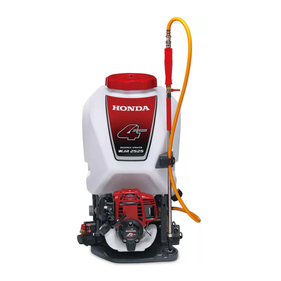
3. COMPONENT IDENTIFICATION CHEMICAL TANK CAP SPRAYER HOSE CHEMICAL TANK SHOULDER HARNESS CHEMICAL TANK DRAIN CAP FRAME NUMBER FUEL RETURN TUBE (TRANSPARENT TUBE) NOZZLE LEVER STARTFR GRIP NOZZLE PIPE CHOKE LEVER MUFFLER PRIMING PUMP NOZZLE HOLDER ENGINE OIL FILLER CAP PRESSURE DlAL AIR CLEANER (WJR2525) -
Page 20: Pre-Operation For Starting
1. Assembling a nozzle. 1. Connect the sprayer hose to the nozzle lever. 2. Connect the nozzle pipe to the nozzle lever. NOZZLE PIPE NOZZLE PIPE WJR1525: WJR2525: SPRAYER HOSE SPRAYER HOSE NOZZLE LEVER NOZZLE LEVER 3. Connect the nozzle tip to the nozzle pipe. - Page 21 3. Make sure the shoulder harness. Make sure that the bottom hook of the shoulder harness is connected. SHOULDER HARNESS CAUTION: When you put the sprayer on your back, make sure that the shoulder harness is not entangled with the throttle lever. SHOULDER HARNESS THROTTLE LEVER...
- Page 22 Recommended Oil Use 4-stroke motor oil that meets or exceeds the requirements for API service classification SE or later (or equivalent). Always check the API service label on the oil container to be sure it includes the letters SE or later (or equivalent). SAE 10W-30 is recommended for general use.
- Page 23 5. Check the fuel level. Use automotive unleaded gasoline with a Research Octane Number of 91 or higher (a Pump Octane Number of 86 or higher). Never use stale or contaminated gasoline or an oil/gasoline mixture. Avoid getting dirt or water in the fuel tank. •...
- Page 24 1. Place the power sprayer horizontally, and check the outside of the tank if the fuel reaches the upper fuel level. 2. If the fuel level is low, refuel the fuel tank until the level as specified. Remove the fuel tank cap gradually to release a pressurized air in the fuel tank.
- Page 25 6. Check the air cleaner element. Move the choke lever to the CLOSED position. Press the upper tab on the top of the air cleaner cover, and remove the cover. Check the element to be sure it is clean and in good condition. If the element is dirty, clean it (see page 38).
- Page 26 7. Check the throttle cable free play. • Check the throttle cable free play at the tip of the cable by pulling and releasing the throttle lever a few times. It should be 0.5 – 2.5 mm (0.02 – 0.10 in.) at the tip of the throttle cable. FIXING NUT FREE PLAY: 0.5 –...
- Page 27 9. Check the chemical tank and tank filters. 1. Remove the tank cap and drain cap. Check the caps and packings for cracks or damage. If they are damaged, replace them. 2. Remove the two tank filters. Check the tank filters for clog or damage. •...
-
Page 28: Starting The Engine
“STARTING” TAB PRESSURE DIAL 2. Turn the nozzle lever to the CLOSED position. CLOSED WJR2525: WJR1525: CLOSED NOZZLE LEVER NOZZLE LEVER 3. To start a cold engine, move the choke lever to the CLOSED position. To restart a warm engine, leave the choke lever in the OPEN position. - Page 29 4. Press the priming pump several FUEL RETURN TUBE (TRANSPARENT TUBE) times until a flow in the fuel return tube (transparent tube) is visually noticed. PRIMING PUMP 5. Make sure that the throttle lever is the SLOW position. THROTTLE LEVER SLOW 6.
- Page 30 7. Hold the engine top cover securely and pull the starter grip lightly until you feel resistance, then pull it briskly in the direction of the arrow as shown below. Return the starter grip gently. • Be sure that the people and pets are away from the power sprayer especially behind you, before pulling the starter grip.
-
Page 31: High Altitude Operation
Hot Restart If the engine is operated at higher ambient temperatures then turned off and allowed to sit for a short time, it may not restart on the first pull. If necessary, use for following procedure: IMPORTANT SAFETY PRECAUTION Turn the engine switch to the OFF position before performing the following procedure. -
Page 32: Stopping The Engine
To stop the engine in an emergency, simply turn the engine switch to the OFF position. Under normal conditions, use the following procedure. 1. Turn the nozzle lever to the CLOSED position. WJR2525: CLOSED WJR1525: CLOSED NOZZLE LEVER NOZZLE LEVER 2. Move the throttle lever to the SLOW position. - Page 33 3. Turn the engine switch to the OFF position. ENGINE SWITCH...
-
Page 34: Operation
7. OPERATION 1. Start the engine (see page 25). 2. Make sure that the throttle lever is the SLOW position. THROTTLE LEVER SLOW 3. Put the power sprayer on a flat table. 4. Make sure that the shoulder harness is not entangled with the throttle lever, and remove the nozzle from the nozzle holder. - Page 35 MARK (ALIGNING POINT) “HIGH PRESSURE” TAB “HERBICIDE” TAB PRESSURE DIAL “INSECTICIDE” TAB 6. Move the throttle lever at the desired position with the nozzle lever moved while observing the spray. WJR1525: CLOSED OPEN NOZZLE LEVER WJR2525: FAST NOZZLE LEVER CLOSED...
- Page 36 During operation • Do not point the nozzle at others. • Pay attention to the rest of agricultural chemicals in the tank. The operation of the sprayer with a little chemicals in the tank will damage the pump.
- Page 37 After operation When handling agricultural chemicals, follow the directions of the manufacturer or distributor. Also, follow the laws and regulations. 1. Stop the engine (see page 29). 2. After the engine cooled, remove the chemical tank drain cap to drain the agricultural chemicals in the chemical tank.
-
Page 38: Maintenance
8. MAINTENANCE Periodic inspection and adjustment of the power sprayer are essential if high level performance is to be maintained. Regular maintenance will also help to extend service life. The required service intervals and the kind of maintenance to be performed are described in the table in the following page. - Page 39 Maintenance schedule REGULAR SERVICE PERIOD (3) First Every Every Every Every Perform at every indicated Each month 3 months 6 months year two years month or operating hour interval, whichever comes first. 10 Hrs. 25 Hrs. 50 Hrs. 100 Hrs. 300 Hrs.
- Page 40 1. Changing oil Drain the oil while the engine is still warm to assure rapid and complete draining. Place the power sprayer on a firm level surface with the engine stopped. 1. Check the fuel tank cap is tightened securely. 2.
- Page 41 2. Air cleaner service A dirty air cleaner will restrict air flow to the carburetor. To prevent carburetor malfunction, service the air cleaner regularly. Service more frequently when operating the power sprayer in extremely dusty areas. Never use gasoline or low flash point solvents for cleaning the air cleaner element.
- Page 42 3. Spark plug service Recommended spark plug: CMR4H (NGK) CAUTION: Never use a spark plug of incorrect heat range. To ensure proper engine operation, the spark plug must be properly gapped and free of deposits. 1. Loosen the 5 mm hex bolt, then remove the top cover. Do not pull the starter grip and start the engine without the top cover.
- Page 43 2. Remove the spark plug cap. Remove any dirt from around the spark plug area. 3. Use the proper size spark plug wrench to remove the spark plug. If the engine has been running, the muffler will be very hot. Be careful not to touch the muffler.
- Page 44 7. After the spark plug is seated, tighten with a spark plug wrench to compress the washer. SPARK PLUG WRENCH NOTE: When installing a new spark plug, tighten 1/2 turn after the spark plug seats to compress the washer. When reinstalling a used spark plug, tighten 1/8 – 1/4 turn after the spark plug seats to compress the washer.
- Page 45 4. Fuel filter service Gasoline is extremely flammable and is explosive under certain conditions. Do not smoke or allow flames or sparks in the area. 1. Check the engine oil filler cap is tightened securely. 2. Remove the fuel tank cap and drain the fuel into the container by inclining the power sprayer toward the fuel filler neck.
- Page 46 5. Fuel tank cleaning Gasoline is extremely flammable and is explosive under certain conditions. Do not smoke or allow flames or sparks in the area. 1. Check the engine oil filler cap is tightened securely. 2. Remove the fuel filler cap and drain the fuel into the container by inclining the engine toward the fuel filler neck.
- Page 47 7. Disassembly and maintenance of the nozzle If the sprayer sprays irregularly, disassemble the nozzle and maintain it. • If there is any stain or block, clean it off. • If the nozzle is damaged, replace it. WJR1525: WJR2525: NOZZLE NOZZLE...
-
Page 48: Transporting/Storage
9. TRANSPORTING/STORAGE Transporting • To avoid severe burns or fire hazards, let the engine cool before transporting the power sprayer or storing it indoors. • When transporting the power sprayer, tighten the fuel filler cap to prevent fuel spillage. Fuel vapor or spilled fuel may ignite. Storage Before storing the power sprayer for an extended period;... - Page 49 WJR1525: Push and hold the pump drain (yellow) button for ten seconds. PUMP DRAIN (YELLOW) BUTTON c. Start the engine (see page 25). d. Move the throttle lever between the FAST position and the SLOW position (see page 32), and hold it there for ten seconds to drain the pump chamber completely.
- Page 50 c. Press the priming pump several times until all fuel left in the fuel return tube is returned into the fuel tank. d. Tilt the engine toward the fuel filler neck again to drain the fuel left in the fuel tank into the container. e.
-
Page 51: Troubleshooting
10. TROUBLESHOOTING When the engine will not start: 1. Is the engine switch in the ON position? 2. Is there fuel in the fuel tank? 3. Is gasoline reaching the carburetor? To check, press the priming bulb several times. 4. Is the spark plug in good condition? Remove and inspect the spark plug. -
Page 52: Specifications
9.4 kg (20.7 Ibs) 9.2 kg (20.3 Ibs) Chemical tank capacity 25 L Pump Type WJR1525 Horizontal single piston WJR2525 Horizontal opposed twin pistons Max. pressure 1.5 Mpa (at 7,000 rpm) 2.5 Mpa (at 6,300 rpm) Suction 5.2 L/min (at 7,000 rpm) 7.1 L/min (at 6,300 rpm) - Page 53 Engine Model GX25T Engine type 4-stroke, overhead cam, 1 cylinder Displacement 25.0 cm (1.5 cu-in) Bore x Stroke 35.0 x 26.0 mm (1.4 x 1.0 in) Engine net power 0.72 kW (1.0 PS)/7,000 rpm (in accordance with SAE J1349*) Engine max. net torque 1.0 N·m (0.10 kgf-m)/5,000 rpm (in accordance with SAE J1349*) Cooling system...
-
Page 54: Major Honda Distributor Addresses
MAJOR Honda DISTRIBUTOR ADDRESSES For further information, please contact Honda Customer Information Centre at the following address or telephone number: ADRESSES DES PRINCIPAUX CONCESSIONNAIRES Honda Pour plus d’informations, s’adresser au Centre d’informations clients Honda à l’adresse ou numéro de téléphone suivants : ADRESSEN DER WICHTIGSTEN Honda-HAUPTHÄNDLERS Weitere Informationen erhalten Sie gerne vom Honda-Kundeninformationszentrum unter der folgenden Adresse oder Telefonnummer:... - Page 55 AUSTRIA CROATIA FINLAND Honda Motor Europe (North) Hongoldonia d.o.o. OY Brandt AB. Hondastraße 1 Jelkovecka Cesta 5 Tuupakantie 7B 2351 Wiener Neudorf 10360 Sesvete — Zagreb 01740 Vantaa Tel. : +43 (0)2236 690 0 Tel. : +385 1 2002053 Tel. : +358 20 775 7200 Fax : +43 (0)2236 690 480 Fax : +385 1 2020754 Fax : +358 9 878 5276...
- Page 56 HUNGARY MALTA PORTUGAL Motor Pedo Co., Ltd. The Associated Motors Honda Portugal, S.A. Company Ltd. Kamaraerdei ut 3. Rua Fontes Pereira de Melo 16 New Street in San Gwakkin Road 2040 Budaors Abrunheira, 2714-506 Sintra Mriehel Bypass, Mriehel QRM17 Tel. : +36 23 444 971 Tel.
- Page 57 SERBIA & Tenerife province UKRAINE MONTENEGRO (Canary Islands) Honda Ukraine LLC Automocion Canarias S.A. 101 Volodymyrska Str. - Build. 2 Bazis Grupa d.o.o. Carretera General del Sur, KM. 8,8 Kyiv 01033 Grcica Milenka 39 38107 Santa Cruz de Tenerife Tel. : +380 44 390 1414 11000 Belgrade Tel.
-
Page 58: Ec Declaration Of Conformity" Content Outline
"EC Declaration of Conformity" CONTENT OUTLINE "CE-Déclaration de conformité" DESCRIPTION DE TABLE DES MATIERES "EU-Konformitätserklärung" INHALTSÜBERSICHT DESCRIPCIÓN GENERAL DEL CONTENIDO DE LA "Declaración de Conformidad CE" *1: see specification page. *1: Siehe Spezifikationen-Seite é á *1: voir page de sp cifications *1: consulte la p gina de las... - Page 62 300.2009.10 36YG9610 Printed in Japan 00X36-YG9-6100...
Need help?
Do you have a question about the WJR1525 and is the answer not in the manual?
Questions and answers