Table of Contents
Advertisement
Quick Links
Advertisement
Table of Contents

Related Manuals for Honda Power Products FR600


Summary of Contents for Honda Power Products FR600
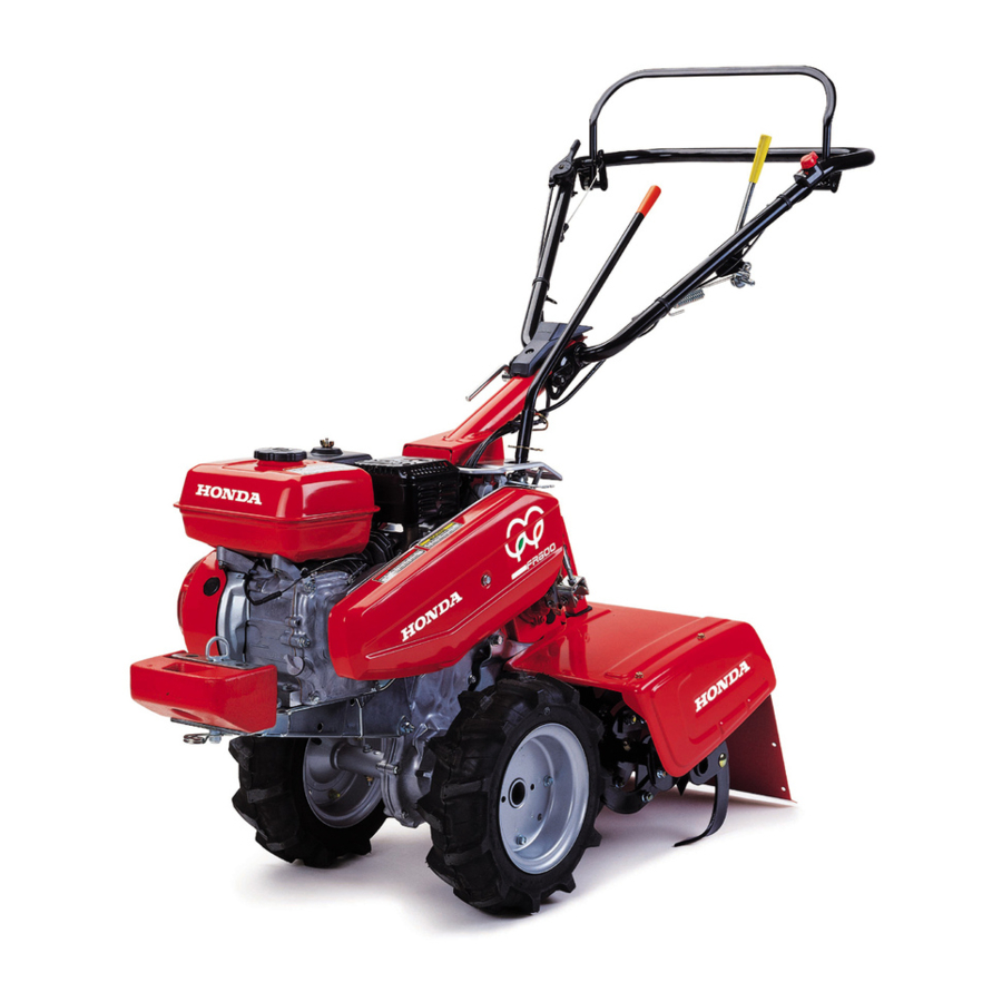
- Page 2 Thank you for purchasing a Honda tiller. This manual covers operation and maintenance of FR600 and FR800. All information in this publication is based on the latest product information available at the time of printing. FR800 The illustrations in this manual are based on: Honda Motor Co., Ltd.
-
Page 3: Table Of Contents
Main clutch operation ..............15 Rotary clutch operation/tilling ............16 Gear selection ................. 16 Wheel weight installation (optional parts for FR600) ....17 Tire pressure .................. . 17 Rotary attachment inspection ............17 Rotary tine inspection/replacement .......... -
Page 4: Safety Information
SAFETY INFORMATION To ensure safe operation − For your safety and the safety of others, pay special attention to these precautions: Operator responsibility Keep the tiller in good operating condition. Operating a tiller in poor or questionable condition could result in serious injury. Be sure all safety devices are in working order and warning labels are in place. - Page 5 Child safety Keep children indoors and supervised at all times when any outdoor power equipment is being used nearby. Young children move quickly and are attracted especially to the tiller and the tilling activity. Never assume children will remain where you last saw them. Be alert and turn the tiller off if children enter the area.
- Page 6 Fire and burn hazard Gasoline is extremely flammable, and gasoline vapor can explode. Use extreme care when handling gasoline. Keep gasoline out of reach of children. Refuel in a well-ventilated area with the engine stopped. Allow the engine to cool before refueling. Fuel vapor or spilled fuel may ignite.
-
Page 7: Safety Label Locations
SAFETY LABEL LOCATIONS These labels warn you of potential hazards that can cause serious injury. Read the labels and safety notes and precautions described in this manual carefully. If a label comes off or becomes hard to read, contact your Honda dealer for a replacement. -
Page 8: Component Identification
COMPONENT IDENTIFICATION MAIN CLUTCH LEVER THROTTLE LEVER MUFFLER FUEL TANK CAP IGNITION SWITCH FUEL TANK V-BELT COVER DRAG BAR SIDE COVER MUD GUARD ENGINE OIL FILLER ROTARY TINES CAP/DIPSTICK ROTARY CLUTCH WHEEL WEIGHT (FR800 ONLY) LEVER GEARSHIFT LEVER FRAME SERIAL NUMBER AIR CLEANER HANDLE HEIGHT... -
Page 9: Pre-Operation Check
PRE-OPERATION CHECK Engine oil Running the engine with low oil level will cause serious engine damage. Place the tiller on a level surface. Remove the oil filler cap and wipe the dipstick clean. Insert the dipstick into the oil filler neck, but do not screw it in. Check the oil level shown on the dipstick. -
Page 10: Transmission Oil
Transmission oil With the tiller on level ground, remove the oil filler cap and to see check if oil is up to the tip of the dipstick. Add same oil as the engine oil (see page for recommended oil) if necessary. OIL FILLER CAP/DIPSTICK LEVEL GAUGE Air cleaner... -
Page 11: Rotary Oil Level
Rotary oil level Place the tiller on level ground and remove the oil level check bolt. Remove the oil filler cap. The oil level should be up to the lower edge of the check bolt hole. If the level is low, add same oil as the engine oil (see page for recommended oil) until it begins to flow out of the hole. -
Page 12: Fuel
Fuel Remove the fuel filler cap, and check if the fuel is up to the level mark. If the fuel level is low, refill with unleaded gasoline up to the level mark. Use automotive unleaded gasoline with a Research Octane Number of 91 or higher (a Pump Octane Number of 86 or higher). - Page 13 Gasoline spoils very quickly depending on factors such as light exposure, temperature and time. In worst cases, gasoline can be contaminated within 30 days. Using contaminated gasoline can seriously damage the engine (carburetor clogged, valve stuck). Such damage due to spoiled fuel is disallowed from coverage by the warranty.
-
Page 14: Starting The Engine
STARTING THE ENGINE Exhaust contains poisonous carbon monoxide gas; exposure can cause loss of consciousness and may lead to death. Never run the engine in an enclosed or confined area. The muffler becomes very hot during operation and remains hot for a while after stopping the engine. - Page 15 Move the throttle lever about 30 degrees from the extreme right (idle position). THROTTLE START LEVER Make sure the main clutch is disengaged and the transmission is in neutral. Pull the starter grip lightly until you feel resistance, then pull briskly in the direction of the arrow as shown.
-
Page 16: Tiller Operation
TILLER OPERATION BEFORE ADJUSTING THE HANDLEBAR, BE SURE THE ENGINE IS OFF. Handlebar height adjustment Before adjusting the handlebar, place the tiller on the firm level ground to prevent the handle from collapsing accidentally. To adjust the handlebar height, HEIGHT ADJUSTER KNOB loosen the adjuster knob, select the appropriate holes in the handle column and handlebar... -
Page 17: Rotary Clutch Operation/Tilling
Rotary clutch operation/tilling To work the tiller Start the engine. DISENGAGED With the throttle at idle and the main clutch disengaged, select a forward gear. ENGAGED Return the throttle to the engine start position (about 30° from idle), and engage the main clutch. Move the rotary clutch forward (engaged position) and the tines will turn. -
Page 18: Wheel Weight Installation (Optional Parts For Fr600)
Wheel weight installation (optional parts for FR600) The wheel weights improve traction on soft or marshy ground. To install the weights, insert two bolts and secure them with the nuts supplied. Tighten the bolts and nuts securely to prevent them from loosening during operation. -
Page 19: Rotary Tine Inspection/Replacement
Rotary tine inspection/replacement Wear heavy gloves to protect your hands. Check for worn, bent or other damaged rotary tines. Check for damage or loose bolts and nuts. Tighten and/or replace them if necessary. Use only a genuine Honda replacement rotary tine. C type Directions of bolts/nuts Directions of rotary tines... - Page 20 D and U types Directions of bolts/nuts Directions of rotary tines For rotary tines A/G and B’/G’: Rotary tines D/G and B’/D’: From outside in Toward outside For others: From inside out Others: Toward inside A’ C’ E’ F’ BOLTS NUTS/WASHERS B’...
- Page 21 Rotary tine arrangement (D and U types only) For best result, the rotary tines should be arranged according to the type of work to be done. The following will aid in arranging the rotary tines to suit your operating condition: Type of work Attachment Tine arrangement...
-
Page 22: Handling Tips
Handling tips Adjust the handlebar height to a comfortable position (waist height for normal tilling). The drag bar should always be used when tilling. It enables you to compensate for the hardness of the soil. The ideal height of the drag bar will depend on the type of soil being tilled and soil conditions at the time of tilling. -
Page 23: Stopping The Engine
STOPPING THE ENGINE MAIN CLUTCH LEVER DISENGAGED To stop the engine in an emergency, release the main clutch lever and turn the igniton switch OFF. Release the main clutch lever and move the shift lever to the ‘‘N’’ (Neutral) position. Move the throttle to the idle po- GEARSHIFT LEVER sition (Extreme right). - Page 24 Carburetor Modification for High Altitude Operation At high altitude, the standard carburetor air-fuel mixture will be too rich. Performance will decrease, and fuel consumption will increase. A very rich mixture will also foul the spark plug and cause hard starting. Operation at an altitude that differs from that at which this engine was certified, for extended periods of time, may increase emissions.
-
Page 25: Maintenance
MAINTENANCE The purpose of the maintenance schedule is to keep the tiller in the best operating condition. Inspect or service as scheduled in the table (see page Shut off the engine before performing any maintenance. Exhaust contains poisonous carbon monoxide gas; Exposures cause loss of consciousness and may lead to death. -
Page 26: Emission Control System Information
EMISSION CONTROL SYSTEM INFORMATION Source of Emissions The combustion process produces carbon monoxide, oxides of nitrogen, and hydrocarbons. Control of hydrocarbons and oxides of nitrogen is very important because, under certain conditions, they react to form photochemical smog when subjected to sunlight. Carbon monoxide does not react in the same way, but it is toxic. - Page 27 Problems That May Affect Emissions If you are aware of any of the following symptoms, have your engine inspected and repaired by your servicing dealer. Hard starting or stalling after starting. Rough idle. Misfiring or backfiring under load. Afterburning (backfiring). Black exhaust smoke or high fuel consumption.
- Page 28 Maintenance Follow the maintenance schedule (see page ). Remember that this schedule is based on the assumption that your machine will be used for its designed purpose. Sustained high-load or high-temperature operation, or use in unusually wet or dusty conditions, will require more frequent service.
- Page 29 Air Index An Air Index Information hang tag/label is applied to engines certified to an emission durability time period in accordance with the requirements of the California Air Resources Board. The bar graph is intended to provide you, our customer, the ability to compare the emissions performance of available engines.
-
Page 30: Maintenance Schedule
Maintenance schedule REGULAR SERVICE PERIOD (3) First Every Every Every Each month 3 months 6 months year ITEM Perform at every indicated month or operating interval, 20 hrs. 50 hrs. 100 hrs. 300 hrs. whichever comes first. Engine oil Check level Change Transmission oil Check level... -
Page 31: Engine Oil Change
(See page for recommended oil). Reinstall and tighten the filler cap. Oil capacity: FR600 : 0.6 (0.6 US qt , 0.5 Imp qt) FR800 : 1.1 (1.2 US qt , 1.0 Imp qt) OIL DRAIN BOLT... -
Page 32: Air Cleaner Service
Air cleaner service A dirty air cleaner will restrict air flow to the carburetor. To prevent carburetor malfunction, service the air cleaner regularly. Service more frequently when operating the engine in extremely dusty areas. Never use gasoline or low flash point solvents for cleaning the air cleaner element. -
Page 33: Sediment Cup Cleaning
Sediment cup cleaning Gasoline is extremely flammable and is explosive under certain conditions. Do not smoke or allow flames or sparks in the area. After installing the sediment cup, check for leaks, and make sure the area is dry before starting the engine. Turn the fuel cock lever OFF. -
Page 34: Rotary Oil Level
Rotary oil level Place the tiller on level ground and remove the oil level check bolt. Remove the oil filler cap. The oil level should be up to the lower edge of the check bolt hole. If the level is low, add oil until it begins to flow out of the hole (see page for recommened oil). - Page 35 Visually inspect the spark plug. Discard it if the insulator is cracked or chipped. Clean the spark plug with a wire brush if it is to be reused. Measure the plug gap with a feeler gauge. Correct as necessary by bending the side electrode. The gap should be: 0.70 0.80 mm (0.028 0.031 in) −...
-
Page 36: Spark Arrester Maintenance (Optional Parts)
Spark arrester maintenance (optional parts) The muffler becomes very hot during operation and remains hot for a while after stopping the engine. Be careful not to touch the muffler while it is hot. The spark arrester must be serviced every 100 operating hours to maintain its efficiency. -
Page 37: Throttle Cable Adjustment
Throttle cable adjustment Loosen the lock nut and turn the adjusting nut until the free play in the throttle lever at the end of the THROTTLE LEVER lever is between: 5.0 10.0 mm − (1/4 3/8 in) − After adjusting the free play, tighten the lock nut securely. -
Page 38: Drive Belt Adjustment
Drive belt adjustment The drive belt must be inspected FR600: 65 70 mm (2.6 2.8 in) − − FR800: 52 57 mm (2.0 2.2 in) − − regularly for correct tension. The drive belt, which is slipping on its pulleys, will result in loss of power and premature wear or damage to the drive belt. - Page 39 Adjust the belt-to-belt stopper clearances as shown. FR800 FR600 ○ ○ A D ○ ○ A C 1.0 3.0 mm − 3.0 4.0 mm − (0.04 0.12 in) − (0.12 0.16 in) − 3.0 5.0 mm − 2.0 4.0 mm −...
-
Page 40: Upper Chain Adjustment
Check that the free play of the main clutch lever at the tip of the lever when the lever is released. Free play should be: FR600: 25.0 30.0 mm (0.98 1.18 in) − − FR800: 5.0 10.0 mm (0.20 0.39 in) -
Page 41: Transporting/Storage
TRANSPORTING/STORAGE When transporting the tiller, turn the fuel cock lever OFF and keep the tiller level to prevent fuel spillage. Fuel vapor or spilled fuel may ignite. After use, park the tiller on a level surface. Be sure the storage area is well-ventilated, do not allow flames or sparks in the storage area. -
Page 42: Troubleshooting
TROUBLESHOOTING When the engine will not start ; Is there enough fuel ? Is the fuel cock lever ON ? Is the engine switch ON ? Is gasoline reaching the carburetor ? To check, loosen the drain screw with the fuel cock lever on. Fuel should flow out freely. -
Page 43: Specifications
SPECIFICATIONS Model FR600 FR800 Type C, D, U Dimensions, (Length) 1,460 mm (57.5 in) 1,420 mm (55.9 in) (Height) 1,240 mm (48.8 in) 1,230 mm (48.4 in) (Width) 560 mm (22.0 in) 705 mm (27.8 in) Dry mass [weight] 90 kg (198 lbs) -
Page 44: Major Honda Distributor Addresses
MAJOR Honda DISTRIBUTOR ADDRESSES For Canadian NAME OF FIRM (COMPANY) ADDRESS TEL: FAX: Honda Canada Inc. 715 Milner Avenue Tel: 1-888-946-6329 Toronto ON Fax: 1-887-939-0909 M1B 2K8 For Australian NAME OF FIRM (COMPANY) ADDRESS TEL: FAX: Honda Australia Motorcycle and 1954-1956 Hume Highway Tel: (03) 9270 1111 Power Equipment Pty.
Need help?
Do you have a question about the FR600 and is the answer not in the manual?
Questions and answers