
Related Manuals for Moeller XN-PLC-CANopen


Summary of Contents for Moeller XN-PLC-CANopen
- Page 1 Modular PLC XN-PLC-CANopen Hardware, Engineering and Functional Description 02/05 AWB 2724-1566GB T hink future. Switch to green.
- Page 2 No part of this manual may be reproduced in any form (printed, photocopy, microfilm or any other process) or processed, duplicated or distributed by means of electronic systems without written permission of Moeller GmbH, Bonn. Subject to alteration without notice.
- Page 3 Warning! Dangerous electrical voltage! Before commencing the installation • Disconnect the power supply of the device. • Ensure a reliable electrical isolation of the low voltage for the 24 volt supply. Only use power supply units complying with • Ensure that devices cannot be accidentally restarted. IEC 60364-4-41 (VDE 0100 Part 410) or HD 384.4.41 S2.
-
Page 5: Table Of Contents
02/05 AWB2724-1566GB Contents About this manual Device application Abbreviations and symbols Additional documentation Layout of the XN-PLC System and field voltage XI/ON I/O module CPU functions – Operating mode switch – SET button – APPLICATION switch – LED status indicator 1 –... -
Page 6: Led Status Indicator
02/05 AWB2724-1566GB Contents Test and commissioning – Breakpoint/single-step mode – Single-cycle mode – Forcing variables and I/Os – XSoft status indication System events Timer interrupt Creating and transferring boot project Downloading/updating the operating system Diagnostics User program source code Browser commands Calling browser commands Using and evaluating browser commands –... - Page 7 02/05 AWB2724-1566GB Contents Programming through CANopen network (routing) Prerequisites Notes Addressing Procedure PLC combinations for routing Number of communication channels 10 RS 232 interface in transparent mode Appendix Dimensions Technical data Stichwortverzeichnis...
- Page 8 02/05 AWB2724-1566D...
-
Page 9: Device Application
About this manual Device application Additional documentation The XN-PLC-CANopen, referred to as XN-PLC below, is intended In some places this manual contains references to more detailed for use in machine and plant control systems. The PLC has an descriptions in other manuals, which are described with their title RS 232 programming device (service) and a built-in CANopen field and documentation number (e.g. - Page 10 02/05 AWB2724-1566GB...
-
Page 11: System And Field Voltage
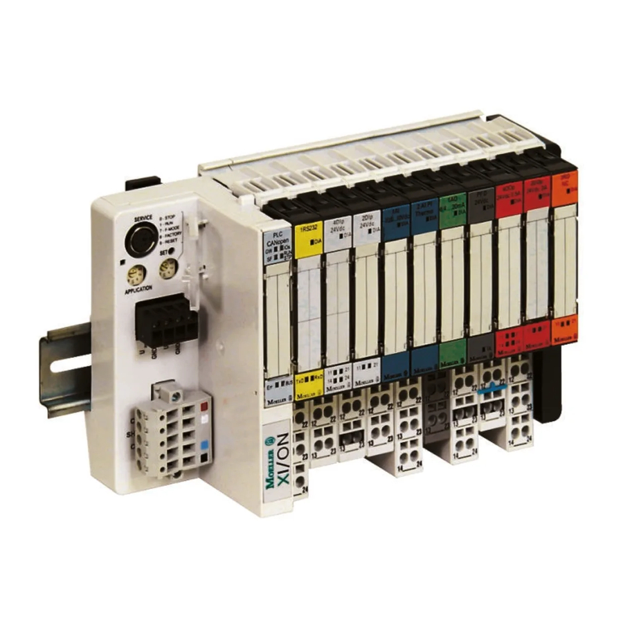
1. Figure 2: Operating mode switch for RUN, STOP, etc. Table 1: Operating mode switch functions Switch Function position Figure 1: Layout of the XN-PLC-CANopen a SET button STOP b LED display 1 c I/O module d End plate STOP... -
Page 12: Set Button
02/05 AWB2724-1566GB Layout of the XN-PLC SET button Table 2: LED status indicator 1 Meaning The SET button is enabled only in connection with setting 8 and 9 of the operating mode switch. When you press the SET button, setting 8 or 9 becomes active (a table 1). Green Rated field voltage U is in valid range... -
Page 13: Real-Time Clock
02/05 AWB2724-1566GB CPU functions LED status indicator 2 Real-time clock The XN-PLC features a real-time clock, which can be referenced in the user program using the functions in the SysLibRTC library, for example to read or set the time. The XN-PLC does not support functions SysRtcCheckBattery and SysRtcGetHourMode! The functions are described in the online help and in the SysLibRtc.pdf file. -
Page 14: Service (Programming) Interface
Layout of the XN-PLC Changing segment allocation Service (programming) interface Select PLC type XN-PLC-CANopen. Select menu Project l You can use this interface: Options to open the Options dialog. In the Category field select Build and enter a “12” in the Number of data •... -
Page 15: Canopen Fieldbus Interface
02/05 AWB2724-1566GB CPU functions CANopen fieldbus interface Properties of the CANopen cable Use only cable approved for CANopen applications and with the The XN-PLC can be connected to the CANopen bus through the following characteristics: isolated ISO 11898 interface. The device can be operated as CAN master or CAN device. - Page 16 02/05 AWB2724-1566GB...
-
Page 17: Mounting The Xn-Plc
02/05 AWB2724-1566GB 2 Mounting Mounting the XN-PLC Mounting the XI/ON modules Hook the XN-PLC onto the mounting rail from below. The XI/ON modules consist of a base module and an electronics Pull the locking slider upwards. module. Press the top of the XN-PLC against the mounting rail. Connect the system’s base module with the PLC from the right- Push the locking slider down again. - Page 18 02/05 AWB2724-1566GB...
-
Page 19: Control Panel Layout
02/05 AWB2724-1566GB 3 Engineering Control panel layout Preventing interference The layout of the components inside the control panel is a major Cable routing and wiring factor for achieving interference-free functioning of the plant or Cables are divided into the following categories: machinery. -
Page 20: Lighting Protection
02/05 AWB2724-1566GB Engineering • Equipotential bonding/earthing Lighting protection • Shielding External lightning protection • Using overvoltage protection devices All cables routed outside buildings must be shielded. Metal conduit is best for this purpose. Fit signal cables with overvoltage Please consult the following manuals for advice on cable routing protection, such as varistors or other surge voltage protectors. -
Page 21: Switch-On Behaviour
02/05 AWB2724-1566GB 4 Using the XN-PLC Switch-on behaviour Configuring the start-up behaviour with XSoft After switching on the supply voltage, the PLC checks whether a The start-up behaviour settings define mainly the handling of the boot project is loaded in flash memory. If it is, and the operating retentive variables. -
Page 22: Program Start
02/05 AWB2724-1566GB Using the XN-PLC Program start Program stop (RUN l STOP) When a program starts, the XN-PLC checks whether the When you set the operating mode switch to STOP, the CPU configured inputs and outputs match the physically present ones. changes to STOP state, as soon as the program cycle is completed. -
Page 23: Reset
02/05 AWB2724-1566GB Reset Reset Test and commissioning There are three different Reset commands: The PLC supports the following test and commissioning features: • Warm reset • Breakpoint/single-step mode • Cold reset • Single-cycle mode • Full reset • Forcing • Online modification table 7 shows the commands to use for initializing a retentive •... -
Page 24: Xsoft Status Indication
02/05 AWB2724-1566GB Using the XN-PLC XSoft status indication Timer interrupt • The signal states of the physical, Boolean inputs are displayed The timer interrupt is triggered after an adjustable delay of 500 to in both the CPU’s RUN state and in STOP. 2500000 microseconds. -
Page 25: Creating And Transferring Boot Project
02/05 AWB2724-1566GB Creating and transferring boot project Creating and transferring boot project Boot projects are created by loaded user projects (programs) and written to flash memory. A power failure will clear the user project from memory. The PLC then continues to work with a copy of the boot project. -
Page 26: Downloading/Updating The Operating System
Click the OS-File button and select the required operating You can replace the XN-PLC’s operating system (OS) with a current system file (*.hex). version, which is always available for download at the Moeller website (http://www.moeller.net/support). It is also included on each XSoft Service Pack CD. - Page 27 02/05 AWB2724-1566GB Downloading/updating the operating system Figure 27:Warning during download Wait for the following dialog. Figure 28:OS successfully transferred to the PLC Click Exit. Because the PLC is rebooted after every OS download, the message Communication interrupted may appear after the OS has been downloaded to the PLC.
-
Page 28: Diagnostics
02/05 AWB2724-1566GB Using the XN-PLC Diagnostics You can run diagnostics with the help of the diagnostics function block. The following possibilities are available: Type of diagnostics Function block Library Documentation • Checking the XI/ON modules: XDiag_SystemDiag xSysDiagLib AWB2786-1456GB – Agreement of configured hardware with actual hardware: performed once when the PLC is switched on or after the program has been loaded or started. -
Page 29: Browser Commands
02/05 AWB2724-1566GB 5 Browser commands You can directly access the states and events of the XN-PLC with the browser commands. For a description of the available commands, select the XSoft object organizer’s Resources tab and double-click PLC Browser. Place a “?” before the selected browser command, followed by a space, and press the Enter key. -
Page 30: Using And Evaluating Browser Commands
02/05 AWB2724-1566GB Browser commands Using and evaluating browser commands reflect memd Reflects the command line, for testing communications between As mem, but addresses are added to the start address of the data browser and PLC. range. 'reflect ?' is not transferred to the PLC! Example: Example: Figure 33:Browser command memd... -
Page 31: Dpt
02/05 AWB2724-1566GB Using and evaluating browser commands canload Displays the data pointer table. Displays the utilization of the CANopen field bus. Example: Example: Figure 39:Browser command canload In addition to the browser command, function block CAN_BUSLOAD can be used to determine the CAN bus utilization from the user program.a section “Function CAN_BUSLOAD”page 32 Figure 36:Browser command dpt... -
Page 32: Setnodeid
02/05 AWB2724-1566GB Browser commands SetNodeId reload Changes the node ID of the CANopen field bus. Loads the boot project from flash memory to the user memory. Example: Example: Figure 41:Browser command SetNodeId Figure 43:Browser command reload If you run the reload command again after the XN-PLC is in STOP metrics state, the following information is displayed: Displays specific XN-PLC information. -
Page 33: Getswitchpos
02/05 AWB2724-1566GB Using and evaluating browser commands getswitchpos setrtc Returns the operating mode switch position. Sets or changes the PLC date and/or time. Example: Syntax: <setrtc_YY:MM:DD:DW_HH:MM:SS> Legend: Space The last two digits of the year (00 F YY F 99) Month (01 F YY F 12) Day (01 F DD F 31) Figure 46:Browser command getswitchpos... - Page 34 02/05 AWB2724-1566GB...
-
Page 35: Libraries, Function Blocks And Functions
02/05 AWB2724-1566GB 6 Libraries, function blocks and functions The libraries contain IEC function blocks and functions that you Installing additional system libraries can use, for example, for the following tasks: You can install libraries manually as follows: • Data exchange through the CANopen bus •... -
Page 36: Xn-Plc-Specific Functions
02/05 AWB2724-1566GB Libraries, function blocks and functions Function GETAPPLICATIONSWITCH XN-PLC-specific functions With this function you can query the position of the application switch. After an H signal at input xEnable, the number to which Library XN_PLC_Util.lib the switch is set is displayed. This allows an external program selection. -
Page 37: Establishing A Pc - Xn-Plc Connection
02/05 AWB2724-1566GB 7 Establishing a PC – XN-PLC connection To establish a connection between PC and XN-PLC, the two Communication settings (baud rate) of the CPU devices’ communication parameters must be the same. In the Resources tab, select PLC Configuration. To match them, first adjust the PC’s communication settings to the In the PLC Configuration dialog, click the Other Parameters CPU’s settings. - Page 38 02/05 AWB2724-1566GB...
-
Page 39: Creating A Sample Project
After starting XSoft, create a new file: From the File menu, select New. Figure 59:Selecting the target system The possible target settings are listed. From the pull-down list field, select your target system (in our example XN-PLC-CANopen) and double-click it. -
Page 40: Configuring The Plc
PLC’s configuration in the tree view and further settings in the tabs to the right. Click the plus symbol next to Configuration XN-PLC-CANopen. A further control element, XN-PLC-CANopen [SLOT] is displayed. Click this element. The right editor section now contains three tabs. -
Page 41: Writing A Program
02/05 AWB2724-1566GB Writing a program Figure 63:Viewing the addresses Writing a program In the object organizer, select the POUs tab and double-click the PLC_PRG(PRG) resource. Create the variables declaration and the program as shown in figure 64. Figure 64:Program with declaration Compile the project: From the Project menu, select Rebuild all. - Page 42 02/05 AWB2724-1566GB...
-
Page 43: Prerequisites
02/05 AWB2724-1566GB 9 Programming through CANopen network (routing) Routing means to establish an online connection from a Important programming device (PC) to any (routing-capable) PLC in a CAN The program download with a block size of 4 Kbyte to a network without having to directly connect the programming PLC with an operating system version earlier than 1.03.02 device to the target PLC. -
Page 44: Notes
02/05 AWB2724-1566GB Programming through CANopen network (routing) Notes Procedure • If large files are written to the target PLC or read from the PLC, Connect the PC to a PLC. it is possible that the online connection will be interrupted after Select the target PLC with which you want to communicate for the transfer process has been completed. - Page 45 02/05 AWB2724-1566GB Procedure Example The example below illustrates the procedure for accessing a PLC program. CANopen Figure 68:CAN master parameters Figure 70: Diagnostics possibilities a XC100 with node ID 1 b XC200 with node ID 2 c XN-PLC with node ID 3 You have connected the PC to the PLC with node ID “2”...
-
Page 46: Plc Combinations For Routing
ID term to enter the target ID. Enter the figure 3 and confirm with OK. Log on and carry out the action. PLC combinations for routing The following PLC support routing: From P XC100 XC200 HPT100 XN-PLC-CANopen To O XC100 XC200 HPT100 – – XN-PLC- –... - Page 47 02/05 AWB2724-1566GB 10 RS 232 interface in transparent mode In transparent mode, the data transferred between the XN-PLC and the data terminals (e.g. terminals, printers, PCs and measuring instruments) is not interpreted. Switch the RS 232 serial interface of the XN-PLC (COM1) into transparent mode with the user program.
- Page 48 02/05 AWB2724-1566GB...
-
Page 49: Dimensions
02/05 AWB2724-1566GB Appendix Dimensions 50.6 74.4... -
Page 50: Technical Data
02/05 AWB2724-1566GB Appendix Technical data XION-PLC-CANopen General Standards and regulations IEC/EN 61131-2 EN 50178 Ambient temperature °C 0 to +55 Storage °C –25 to +85 Mounting position Horizontal Relative humidity, no condensation (IEC/EN 60068-2-30) 10 to 95 Air pressure (in operation) 795 to 1080 Vibration resistance 10 to 57 Hz g0.075 mm... - Page 51 02/05 AWB2724-1566GB Technical data XION-PLC-CANopen Supply voltage for the CPU (24 V/0 V) Mains failure bridging Dropout duration Repeat rate Input voltage V DC Permissible range V DC 20.4 to 28.8 Power consumption Up to 26 Residual hum and ripple Maximum power dissipated (without local I/O) Overvoltage protection Polarity protection...
- Page 52 02/05 AWB2724-1566GB Appendix XION-PLC-CANopen CANopen Maximum data transmission rate bit/s 10 Kbit/s to 1 Mbit/s Electrical isolation Device profile To DS301V4 PDO type Asyn., cyc., acyc. Connection Terminal block, 5-pin Bus termination resistors External Stations Up to 126 Watchdog RTC (real-time clock)
- Page 53 02/05 AWB2724-1566GB Index Addressing, PLC on CANopen fieldbus ... . . 40 Field voltage ......7, 16 Application routine .
- Page 54 02/05 AWB2724-1566GB Index Program stop ....... .18 Program, creating ......37 Programming cable .
Need help?
Do you have a question about the XN-PLC-CANopen and is the answer not in the manual?
Questions and answers