Advertisement
Quick Links
QUICK START
GUIDE
Part #23-AS-799 US-English v1.0 03-April-19
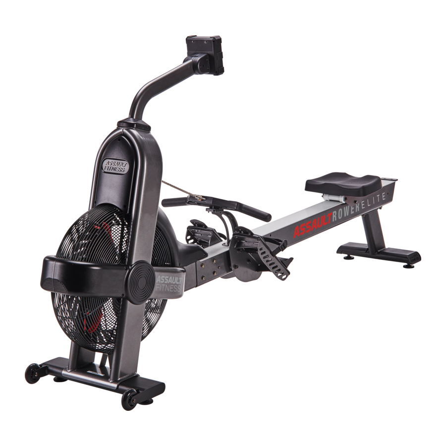
Console Mast Assembly
Console (714)
Console Pivot Covers (716)
Foot Platform - Left (732-A)
Seat Assembly (773-A)
Beam End Cap (707)
Rear Leg Assembly (710-A)
Beam Assembly
*NOTE: CHAIN IS INSTALLED FROM BEAM ASSEMBLY TO MAIN FRAME; MAKE NOTE DURING ASSEMBLY
HARDWARE DESCRIPTION
DRAWING QUANTITY
Socket Head Hex Screw
2
M8 x 1.25 x 16mm (304)
Flat Washer
20
Ø19.0OD x Ø8.5ID x 1.2t (305)
Socket Head Hex Screw
8
M8 x 1.25 x 25mm (317)
Socket Head Hex Screw
4
M3 x 0.5 x 8mm (319)
Spring Washer
20
Ø13.3OD x Ø8.2ID x 1.8t (703)
Button Head Hex Screw
8
M8 x 1.25 x 12mm (704)
Button Head Hex Screw
2
M5 x 0.8 x 10mm (708)
Round Head Cross Tapping Screw
2
M3.5 x 10mm Long (709)
Socket Head Hex Screw
11mm Wrench
6
M8 x 1.25 x 40mm (712)
Socket Head Hex Screw
10
M5 x 0.8 x 12mm (715)
Button Head Hex Screw
4
M5 x 0.8 x 20mm Long (738)
ASSEMBLY
Introduction
• The Assault Fitness AirRower Elite requires assembly prior to use. Tools required to complete the initial setup and assembly have
been included in the Assembly Hardware Kit.
• Lift box top off of contents. Remove all loose parts and the hardware kit from the side of the styrofoam carton. Set aside
styrofoam and remove styrofoam from top of frame but leave the main frame assembly and beam assembly in the
styrofoam and proceed to Step 1 below.
• Confirm all parts shown in the section above titled As Shipped are included before attempting assembly of the AirRower Elite.
Assembly Step 1: Front Stabilizer Installation
• Install the Front Stabilizer (711-A) by placing one M8 Flat Washer
(305) and one M8 Spring Washer (703) onto each of the M8 x 1.25
x 16mm Socket Head Hex Screws (304). Loosely thread the screws
through the underside of the Front Stabilizer (711-A) and into the
Main Frame. Secure the screws in place with the 6mm Hex Wrench
(809).
Assembly Step 2: Beam Installation
• With the assistance of a second person, rotate the Main Frame and supporting styrofoam as shown in the figure until they rest
on the floor. NOTE: Be careful and keep the chain in line with the beam as the frame is rotated towards the floor in order
to ensure that the chain does not get kinked or bent.
• Cut the zip tie holding the chain to the lower box, but before doing so, note the warning below:
WARNING: There is tension in the chain which will pull the Beam Assembly towards the Main Frame once
the zip tie is cut.
Console Mast Covers (316)
Front Stabilizer (711-A)
Foot Platform - Right (733-A)
T-Handle Assembly (789-A)
T-Handle Holder
Assembly (737-A)
Main Frame
ASSEMBLY TOOLS
6mm
5mm
4mm
3mm
Hex Wrench
Hex Wrench
Hex Wrench
Hex Wrench
(809)
(808)
(807)
(806)
• Align the Beam Assembly with the Main Frame and slide the beam onto the beam fixing joint as shown.
• Secure the Beam Assembly by placing one M8 Flat Washer (305) and one M8 Spring Washer (703) onto each of the M8
x 1.25 x 12mm Button Head Hex Screws (704). Loosely thread the screws through the Beam Assembly side wall and and
into the Main Frame. Secure the screws in place with the 6mm Hex Wrench (809).
Assembly Step 3: Rear Leg Assembly Installation
• Install the Rear Leg Assembly (710-A) by placing one M8 Flat Washer
(305) and one M8 Spring Washer (703) onto each of the M8 x 1.25 x
25mm Socket Head Hex Screws (317). Loosely thread the screws through
the underside of the Rear Leg Assembly (710-A) and into the Beam
Assembly. Secure the screws in place with the 6mm Hex Wrench (809).
Console Mast Cover
Assembly Step 4: Foot Platform Installation
Mounting Plates (315)
• Install the Foot Platforms (732-A and 733-A) by placing
one M8 Flat Washer (305) and one M8 Spring Washer
(703) onto each of the M8 x 1.25 x 40mm Socket Head Hex
Screws (712). Loosely thread the screws through the inside of
each Foot Platforms (732-A and 733-A) and into the Beam
Assembly. Secure the screws in place with the 6mm Hex
Wrench (809).
Assembly Step 5: Console Mast and Console Installation
• The Computer Mast Cable (810) is pre-installed and should be extending
from the top to the bottom of the Console Mast Assembly. Connect the
top end of the Computer Mast Cable (810) extending from the Console
Mast Assembly Pivot Bracket into the cable extending from the hole in the
backside of the console and carefully tuck the excess cable into the Console
(714).
• Align the mounting holes located in the back of the Console (714) with the
holes in the Console Mast Assembly Pivot Bracket and loosely thread in the
four M5 x 0.8 x 12mm Socket Head Hex Screws (715). Tighten using the
4mm Hex Wrench (807).
• Next, install the Console Pivot Covers (716) using the six M5 x 0.8 x 12mm
Socket Head Hex Screws (715) and tighten using the 4mm Hex Wrench
(807).
• Connect the lower end of the Computer Mast Cable (810) extending from the Console Mast Assembly into the RPM
Sensor and Cable Assembly (802-A) extending from the Main Frame and carefully tuck the excess cable into the Main
2.5mm
Frame or Console Mast Assembly.
Hex Wrench
• Align the mounting plate for the Console Mast (312) with the mounting holes in the Main Frame. Loosely thread two M8
(805)
x 1.25 x 25mm Cap Head Hex Screws (317) through each Console Mast Cover Mounting Plate (315) and Console Mast
Assembly and into the Main Frame. Tighten all screws firmly using the 6mm Hex Wrench (809).
• Finally, install the two Console Mast Covers (316) using the four M3 x 0.5 x 8mm Socket Head Hex Screws (319). and
tighten firmly using the 2.5mm Hex Wrench (805).
•
Assembly Step 6: Seat and End Cap Installation
• Slide the Seat Assembly (773-A) onto the Beam Assembly in the orientation shown. Do not force it on the Beam or you
could risk damaging the wheels.
• Install the End Cap (707) using the two M5 x 0.8 x 10mm Button Head Hex Screws (708) and tighten using the 3mm Hex
Wrench (806). Next install the two M3.5 x 10mm Long Round Head Cross Tapping Screws (709) through the underside of
the beam using a Phillips head screwdriver to complete the installation of the End Cap (707).
Assembly Step 7: T-Handle Holder Installation
• Install the T-Handle Holder Assembly (737-A) using the four M5 x 0.8 x 20mm
Button Head Hex Screws (738) and tighten using the 3mm Hex Wrench (806).
304
305
711-A
703
Assembly Step 8: T-Handle Installation
• Pull the chain forward from the shroud opening
using the connected zip tie.
• Install the T-Handle Assembly (789-A) using
the T-Handle U-Bolt (767), two 1/4-20 UNC
Nuts (717), and two Ø10.0OD x Ø5.5 x 1t Flat
Washers (412) and tighten using the provided
11mm Wrench.
• Cut the zip tie from the chain.
• Place the T-Handle Assembly (789-A) in the
T-Handle Holder.
Assembly Step 9: Leveling the Unit
• Select a suitable space for operation of the AirRower Elite. Move the unit to the desired location by raising the rear stabilizer
off the ground until the transport wheels touch the ground. Slowly push the unit into place. Ensure there is at least 0.5 m
(19.7 in.) of clearance on all sides of the rower.
• Ensure the unit is level and does not rock by adjusting the Leveling Feet. There are two feet on the Front Stabilizer and two
on the Rear Stabilizer. As a starting point, loosen each foot by turning the leveler clockwise (when looking down towards
the leveler), and then loosen the locknuts against the foot base. Check the unit for stability and make any adjustments as
necessary. Once stable, lock the Leveling Feet in place by tightening the jam nut, against the underside of the stabilizer to
lock the current position of each foot.
• Congratulations, your new Assault AirRower Elite is fully assembled and ready for use. Please read all included information,
user guides and warnings before use.
703
305
704
708
707
773-A
709
717
789-A
704
305
703
305
710-A
703
317
712
703
305
732-A
733-A
305
703
712
714
716
810
715
317
315
715
716
715
316
810
802-A
319
316
319
738
737-A
412
767
www.assaultfitness.com
© Assault Fitness 2019
Advertisement

Subscribe to Our Youtube Channel
Related Manuals for Assault Fitness AIRROWER ELITE


Summary of Contents for Assault Fitness AIRROWER ELITE
- Page 1 • Cut the zip tie holding the chain to the lower box, but before doing so, note the warning below: • Select a suitable space for operation of the AirRower Elite. Move the unit to the desired location by raising the rear stabilizer off the ground until the transport wheels touch the ground.
- Page 2 QUICK START GUIDE will then post. Adjust the displayed time value with the UP or DOWN key and press ENTER to confirm. The default rest interval will post. Adjust the value and confirm by pressing ENTER. Run: The console will display the current Work/Rest interval and the timer display will count down for each CONSOLE FEATURES interval.
Need help?
Do you have a question about the AIRROWER ELITE and is the answer not in the manual?
Questions and answers