
Related Manuals for Solahart ATMOS AIR 270


Summary of Contents for Solahart ATMOS AIR 270
- Page 1 HEAT PUMP HEAT PUMP Operation & Installation Manual Operation & Installation Manual...
- Page 2 Preface This manual includes all the necessary information regarding the Installation and maintenance of this product. Please take the time to read it through before operating. When Installing the hot water cylinder, please follow the Instructions as documented in this manual. Once the Installation is complete, check that all connections are secure before the power is turned The installer is to explain to the end user how to operate and maintain the unit in accordance to this Instruction manual.
-
Page 3: Table Of Contents
Content Content 1. Safety Precautions 2. Specifications 2.1) appearance 2.2) characteristic 2.3) principle 2.4) dimensions 2.5) performance parameter 3. Function presentation 4. Installation 4.1) pipeline connection sketch 4.2) transportation 4.3) installation space 4.4) cable connection 4.5) trial running 4.6) s eismic restraints 5. -
Page 4: Safety Precautions
1.Safety Precautions To prevent personal injury and avoid causing damage to the unit, please take the time to read the information documented in this manual. Icon Meaning A wrong operation may lead to serious injury or death. WARNING A wrong operation may lead to injury or loss of material. ATTENTION Icon Meaning... - Page 5 1.Safety Precautions The unit CANNOT be installed near flammable gas. Installation place Ensure that the base you are fixing to is level and strong enough. Fixing the unit This unit requires a circuit breaker. failure to do so could result in an electrical shock or fire.
-
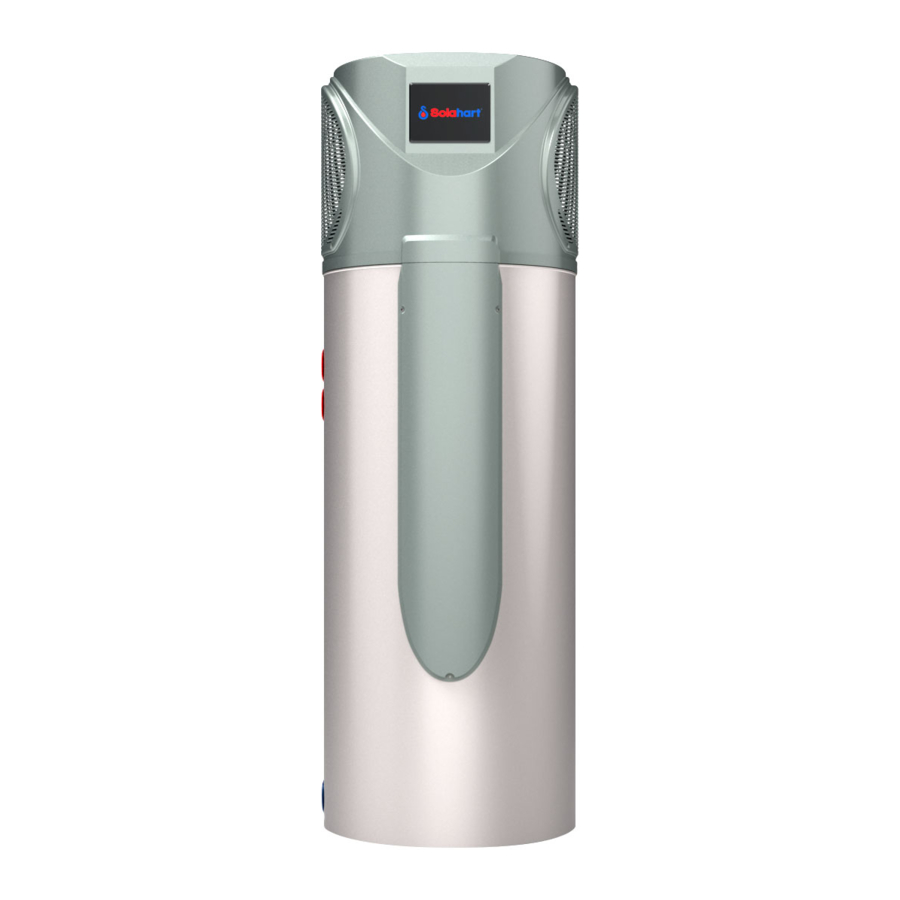
Page 6: Specifications
2.Specifications 2.1 Appearance Air inlet Air outlet controller tank 2.2 Characteristics Smart and efficient unit The operational costs can be up to 75% less than that of an electric water heater, and can be installed in locations which are unsuitable for solar hot water heating. Safe and environmentally friendly Produces no harmful gases along with no open flame, making the unit safe to work with when installing. -
Page 7: Principle
2. Specifications 2.3 Principal High temp. Compressor Compressor Hot water Tank Air from exchanger outside Water exchanger Water supply Low temp. Throttling device System Principle: Refrigerant is compressed into vapor with high temperature and high pressure when it goes through the compressor. On the discharge side of the compressor, the now hot and highly pressurized vapor is cooled down through the heat exchange with the water in the tank until it condenses into a high pressure, moderate temperature liquid. -
Page 8: Dimensions
2. Specifications 2.4 dimensions MODEL: ATMOS AIR 270 Unit mm Model ATMOS AIR 270 A(mm) 1955 B(mm) 1425 C(mm) D(mm) 1195 E(mm) 1095 Hot water outlet Condensation water outlet P&T valve Magnesium Over heating protector Electric heater Cold water inlet 98.5... -
Page 9: Performance Parameter
2. Specifications 2.5 performance parameters Model ATMOS AIR 270 Heating capacity( kW ) Water tank capacity(L) 0.94 Power input( kW ) Running current(A) 240V~/50Hz Power supply Compressor Number rotary Compressor Rated outlet water Temp. Air volume( m /h ) Nosie( dB(A) ) -
Page 10: Function Presentation
3.Function presentation Heating capacity In low ambient conditions the heating output decreases. 3 minutes protection If the unit stops and you re start the unit or turn it on by the manual switch, the unit will not start to run again for approx 3 minutes. This is a protection feature to safe guard the compressor. -
Page 11: Installation
4. Installation Setup cannot affect the building structure and safety. 4.1 Pipeline connection sketch Notice: A pressure realeasing valve isto be fitted in the installation. Spec of P&T valve: Pressure: 0.85MP Temperature: 99 Water Outlet P&T Valve Notice: Tempering valve required Condensate Outlet Magnesium Tap Water... -
Page 12: Transportation
4. Installation WARNING For continued safety of this appliance it mustbe installed, operatedand maintained in accordancewith the manufacturer'sinstructions. If thewater supply pressure exceeds the rated pressure, a pressurereducing valve is tobe fitted wheninstalling the unit. The water may drip from thedischarge pipe ofthe pressure reliefdevice and that this pipe mustbe left opento the atmosphere. -
Page 13: Installation Space
4. Installation 4.3 Installation space Before installation, please ensure that you leave the space as shown below for maintenance. Unit:mm Barrier Air outlet Air inlet Display 1000... - Page 14 4. Installation The Heat pump is designed for external installation; however if possible, installing the system under the house eave or in a sheltered environment may help prolong the life of the system. Rain House eave...
-
Page 15: Cable Connection
4.Installation 4.4 Cable connection This unit requires an isolating switch as required by local by laws. If the power cord is damaged, It must be replaced by a qualified electrician. 4.5 Trial running 4.5.1 Inspection before trial running Check the water supply to the tank and pipe connections for possible leaks. Check that all power connections are secure before switching on. -
Page 16: Usage
5.Usage 5.1 The function diagram of the wire controller 1.Function of wire controller Auxiliary display Main display area area 1£© Function of key Name NO. Button Function ON/OFF Turn on/off the unit. Switch unit running modes or save setting parameters. Mode Clock Set the clock or the timer. - Page 17 Usage Status Name What it means icon Heating Shows that the unit is in heating mode. Eco.heating Shows that the unit is in e co.heating mode. Vacation Shows that the unit is in vacation mode. Shows that the unit is in cooling mode. Cooling Shows that the fan is on and the speed of the fan.
-
Page 18: Usage Of Wire Controller
5.Usage 5.2 Usage of wire controller 5.2.1 Turn ON/OFF the unit Press " " and hold for 0.5s in the standby interface of the wire controller to turn on the unit and at this time the main display area shows the water outlet temperature. Press "... - Page 19 5.Usage Outlet water temperature Heating mode Time Eco.heating mode Press Date Intelligent mode Press Vacation mode Press 5.2.3 Target temperature checking and setting In the standby or running interface, press " " or " " once to check the target temperature of the outlet water.
- Page 20 5.Usage Target temperature Outlet water temperature Time Press once to check the target temperature. Press again to change the target temperature. Press to confirm cancel, then return to the previous interface. 5.2.4 Time setting In the standby or running interface, do as follows to set the time when in heating mode. When press "...
- Page 21 5. Usage Press " " or " " to change the minute The date is flashing parameter. Press" " to confirm. Press once then press to change the month parameter and press to confirm. Press " " or " " to change the dayparameter.
- Page 22 5. Usage Heating mode Outlet water temperature ON 1 Time Press hold for 2s. Press " " and hold for 2s to enter into the next setting without confirm the previous one. ON 2 OFF 1 Press " " and hold for 2s to enter into the next setting without...
- Page 23 5. Usage Example: Running period 1: 8:00~10:00; Running period 2: 16:30~22:00. ON 1 Outlet water temperature Current time Press " " and hold for 2s. Confirm the time after setting. OFF 1 ON 2 Confirm the time after setting. Confirm the time after setting. OFF 2 Successful setting Without saving...
- Page 24 5. Usage 5.2.5.2 In the vocation mode Press " " and hold for 2s to enter into the timer setting interface. The symbol "ON " and the date parameter are flashing at this time. Then set the date in the same way as "2.4 ". Turn off the unit before going Example: Set the start-up date on September 28.(Note: out.
- Page 25 5.Usage 5.2.5.3 If you want to cancel the timer setting ,follow this below Outlet water temperature The "ON" and " 1 " icons are flashing Timer state Pressing " " lasting for 2S press " " to cancel all the operation...
- Page 26 5. Usage 5.2.6 Electric heater setting The electric heater can be turned on when the unit is heating or standby. Press " " once to turn on the electric heater and press " " again to shut it off . Electric heater Electric heater 5.2.7 Fan mode setting...
- Page 27 5. Usage 5.2.8 Keyboard locking Press " " and hold for 5s once to lock the keyboard. Press " " and hold for 5s again to unlock the keyboard. Lock icon Press" " and hold for 5s...
-
Page 28: Maintenance And Repair
6.Maintenance and repair 6.1 Maintenance Check the water supply and air vent frequently, to avoid lack of water or air in the water loop. Clean the water filter periodically, helping the water to stay clean. Lack of water and dirty water can damage the unit. The heat pump will start the water pump per every 72 hrs when it is not running, to avoid freezing. - Page 29 6.Maintenance and repair 6.2 The normal failure and solutions For any malfunctions, please refer to the table below : Display Malfunction Canse Solution Bottom water The water b ottom temp. Sensor Check or change the water temp. Failure is open or short circuit bottom temp.
-
Page 30: Appendix
7.Appendix 7.1 CAUTION 1. To reduce the risk of excessive pressures and temperatures in this water heater, install temperature and pressure protective equipment required by local codes and no less than a combination temperature and pressure relief valve certified by a nationally recognized testing laboratory that maintains periodic inspection of production of listed equipment or materials, as meeting the requirements for Relief Valves and Automatic Gas Shutoff Devices for Hot Water Supply Systems, ANSIZ21.22. -
Page 31: The Method Of Grounding
7.Appendix 7.2 The method of grounding P&T valve use of the P&T valve is used to prevent the temperature or pressure going too high inside the tank. When the temperature or pressure reaches the set value, the valve will open automatically so as to force the pressure or decrease the temperature. -
Page 32: Drain Out The Water
7.Appendix 7.4. Drain out the water Cut out the water supply connection between the tap water supply and the tank by closing the corresponding valve. Open the hot water outlet and then open the drain outlet valve at the same time. The water in the tank will be drained out through the drain outlet. - Page 33 NOTES:...
- Page 34 NOTES:...
- Page 35 NOTES:...
- Page 36 Solahart Industries Registered Office 1 Alan Street, Rydalmere New South Wales 2116 Australia Telephone International Sales: + 61 2 9684 9100 Facsimile International Sales: + 61 2 9684 9180 Email: solahart@solahart.com.au Web: www.solahart.com Code 20180604-0002 Code 20180604-0002...
Need help?
Do you have a question about the ATMOS AIR 270 and is the answer not in the manual?
Questions and answers