Table of Contents
Advertisement
Quick Links
Advertisement
Table of Contents

Subscribe to Our Youtube Channel
Summary of Contents for AP TC5-1V10SA
- Page 1 Environment Control TC5-1V10SA USER'S MANUAL M 890-00167 rev. 06 REV. 01...
-
Page 2: Table Of Contents
Minimum Speed Curve ..........31 Differential Settings ............37 Mist Cooling ..............39 HEATER SETTINGS ............42 ALARM SETTINGS ............47 TEST MODE ..............48 TROUBLESHOOTING GUIDE ........49 TECHNICAL SPECIFICATIONS........53 FACTORY SETTINGS ............ 54 GLOSSARY ..............57 TC5-1V10SA rev.06... -
Page 3: Precautions
DO NOT SPRAY WATER ON THE CONTROLLER FOR CUSTOMER USE Enter the serial number located on the side of the controller below for future reference. TC5-1V10SA Model number: Serial number: TC5-1V10SA rev.06... -
Page 4: Features
FEATURES The TC5-1V10SA is an electronic device used for environmental control in livestock buildings. It allows the user to maintain a specified target tem- perature by controlling the operation of ventilation and heating equipment. One stage of variable speed fans can be connected to the controller, as well as eight stages of constant-speed fans and two stages of either con- stant-speed fans or heating units. - Page 5 CONTROL OF AIR INLET MOVEMENT If the TC5-1V10SA is used in combination with a PF-6 controller, the move- ment of the air inlets can be coordinated with the operation of the fans using a potentiometer located on the panel drive.
-
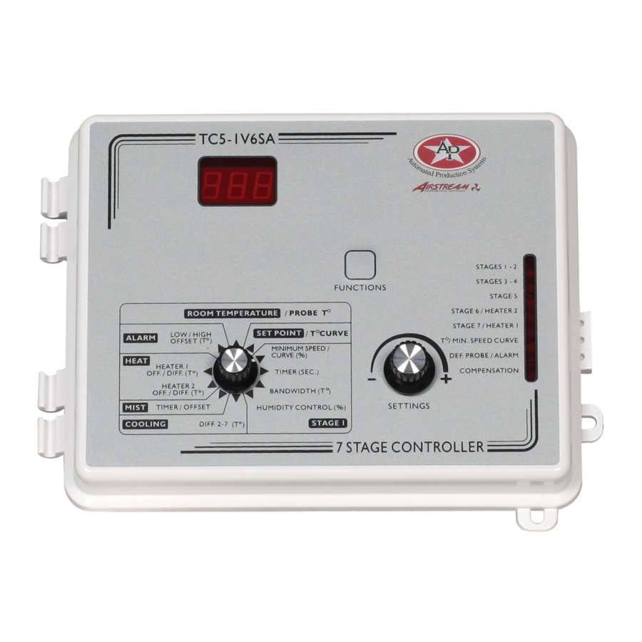
Page 6: Location Of The Controls
LOCATION OF THE CONTROLS TC5-1V10SA rev.06... -
Page 7: Controller Status Leds
Z O N E D H E A T E R S M IS T O F F M IS T O N R E S E R V E D R E S E R V E D R E S E R V E D TC5-1V10SA rev.06... -
Page 8: Installation
ALL WIRING MUST BE DONE BY AN AUTHORIZED ELECTRI- CIAN AND MUST COMPLY WITH APPLICABLE CODES, LAWS AND REGULATIONS. BE SURE POWER IS OFF BEFORE DO- ING ANY WIRING TO AVOID ELECTRICAL SHOCKS AND EQUIP- WARNING MENT DAMAGE. TC5-1V10SA rev.06... -
Page 9: Motor Types
Press the push-button. The cur- rently selected motor type is displayed, alternating with the letters "tYP". Use the adjustment knob to adjust the motor type to the desired value. Return to the Stage 1 bandwidth display by pressing the push-button once again. TC5-1V10SA rev.06... -
Page 10: Heating/Cooling Option
Be sure that probe cables remain isolated from all high voltage sources. In particular, do not route the probe cables through the same electrical knockout as other cables. Do not connect the shield from the probe cable to a terminal or a ground. TC5-1V10SA rev.06... - Page 11 AWG) to ensure the cable entry is liquid tight. Do not ground the shielding. It is preferable to solder the cable joint to ensure a proper contact between the two cables. CAUTION: Do not run probe cables next to other power cables. When crossing over other cables, cross at 90°. TC5-1V10SA rev.06...
- Page 12 If the probe is defective, the letters "PR#" are displayed, alternating with the on/off state of the probe and the letter "P". TC5-1V10SA rev.06...
-
Page 13: Changing The Parameter Settings
St 2 (ii) If, after about 6 seconds, no action is taken by the user, the absolute temperature value is displayed, alternating with "St 2". In this case, the absolute value is: Set Point + Bandwidth + Differential 2. TC5-1V10SA rev.06... -
Page 14: Locking The Parameters Settings
Stage 1 minimum ventilation speed can be modified (as long as the tem- perature curve and the minimum ventilation speed curve are deactived re- spectively). To lock the parameter settings: Set internal switch # 1 to ON. To unlock the parameter settings: Set internal switch # 1 to OFF. TC5-1V10SA rev.06... -
Page 15: Temperature Settings
Set the selection knob to ROOM TEMPERATURE / PROBE T . The room temperature is displayed. Viewing Probe Temperatures The controller can display probe temperatures individually. Probes can also be turned on or off to control the temperature in different parts of the building. TC5-1V10SA rev.06... - Page 16 Turn the adjustment knob clockwise a third notch. The room tem- perature is displayed again. For each individual probe, press the push-button. The temperature reading from probe x is displayed, alternating with the letters "Pr x" and the on/off state of the probe. TC5-1V10SA rev.06...
- Page 17 Press the push-button to access the other probes, etc. NOTE : If you let the display flash for more than 10 seconds, the control- ler resets the minimum and maximum temperatures currently in memory (the display stops flashing to indicate that the reset has been done). TC5-1V10SA rev.06...
-
Page 18: Temperature Set Point
The temperature set point can be adjusted only if the temperature curve is deactivated (see following section). If the curve is activated, the set point alternates with the word "On" when the selection knob is set to SET POINT / CURVE. TC5-1V10SA rev.06... -
Page 19: Temperature Curve
Certain restrictions apply to reduce the risk of errors: − The highest possible day number is 99. − Decreasing day numbers are not allowed. − Increasing temperatures are not allowed. − The temperature variation cannot exceed 3°F (1.6°C) per day. TC5-1V10SA rev.06... - Page 20 Using the adjustment knob, adjust the set point to the desired value. Once the six points of the curve have been specified, activate the curve as explained below. NOTE : Make sure the temperature curve is deactivated before specify- ing new points (see below). TC5-1V10SA rev.06...
- Page 21 Press the push-button to display the points of the curve currently defined until the word OFF appears (thirteen clicks). Turn the adjustment knob clockwise one notch. The word ON flashes on the display indicating that the temperature curve is now activated. Set the selection knob to ROOM TEMPERATURE. TC5-1V10SA rev.06...
- Page 22 Press the push-button to display the points of the curve actually defined until the word ON appears (fourteen clicks). Turn the adjustment knob counterclockwise one notch. The word OFF flashes on the display indicating that the temperature curve is now deactivated. Set the selection knob to ROOM TEMPERATURE. TC5-1V10SA rev.06...
-
Page 23: Ventilation Settings
VENTILATION SETTINGS The TC5-1V10SA controls one stage of variable-speed fans (Stage1), eight stages of constant-speed fans (Stages 2 - 9) and two optional stages of constant-speed fans (Stages 10 & 11). The diagram on the following page shows the operation of the cooling stages. - Page 24 • At Set Point: stage 1 fans reach minimum speed. • Below the Set Point: stage 1 fans stop operating continuously and operate according to the minimum ventilation cycle at minimum speed. TC5-1V10SA rev.06...
- Page 25 TC5-1V10SA ST 11 ST 10 ST 9 ST 8 ST 7 ST 6 ST 5 ST 4 ST 3 ST 2 ST 1 TC5-1V10SA rev.06...
-
Page 26: Minimum Ventilation Cycle
2. To stop the fans, set time on to zero and time off to any value. 3. To run the fans intermittently, set time on to the desired running time and time off to the desired off time. TC5-1V10SA rev.06... - Page 27 Use the adjustment knob to adjust time on to the desired value. Press the push-button. The current time off for Stage 1 flashes on the display, alternating with the letters "Off". Use the adjustment knob to adjust time off to the desired value. TC5-1V10SA rev.06...
-
Page 28: Humidity Compensation
This feature also applies when the minimum ventilation speed is activated. Note that for the compensation to take place, the compensation feature must be activated by the user. When a compensation is applied to the minimum speed, the compensation pilot light turns on. TC5-1V10SA rev.06... - Page 29 Note that the humidity compensation feature must be activated for this to work. Set the selection knob to STAGE 1 — HUMIDITY CONTROL. The current humidity reading is displayed. TC5-1V10SA rev.06...
- Page 30 Set the selection knob to STAGE 1 — HUMIDITY CONTROL. The current humidity reading is displayed. Press the push-button three times. The current on/off state of humidity compensation flashes on the display. Use the adjustment knob to adjust the on/off state to the desired value. TC5-1V10SA rev.06...
-
Page 31: Minimum Speed Curve
When the room temperature rises above the set point, the fans will return to the current minimum speed, calculated according to the minimum speed curve. TC5-1V10SA rev.06... - Page 32 (see example 1). EXAMPLE 1 TEMPERATURE CURVE MINIMUM SPEED CURVE POINT d5 to d19 (adjustable) d20 (not ajustable) POINT TC5-1V10SA rev.06...
- Page 33 Therefore, if you activate the minimum speed curve today, it will effectively be in operation the moment you activate it. In this case, the current minimum speed will be a value between 10% and 20%. TC5-1V10SA rev.06...
- Page 34 The minimum speed curve must be deactivated before specifying the points on the curve (see below). If the curve is activated, the minimum speed alternates with the word "On" when the selection knob is set to MINIMUM SPEED. TC5-1V10SA rev.06...
- Page 35 Press the push-button to display the points of the curve currently defined until the word OFF appears (fourteen clicks). Turn the adjustment knob clockwise by one notch. The word ON flashes on the display indicating that the minimum speed curve is now activated. TC5-1V10SA rev.06...
- Page 36 Press the push-button to display the points of the curve currently defined until the word ON appears (fourteen clicks). Turn the adjustment knob counterclockwise by one notch. The word OFF flashes on the display indicating that the minimum speed curve is now deactivated. TC5-1V10SA rev.06...
-
Page 37: Differential Settings
Use the adjustment knob to adjust the differential to the desired value. Press the push-button. The current differential for Stage 3 flashes on the display, alternating with the letters "St 3". Use the adjustment knob to adjust the differential to the desired value. TC5-1V10SA rev.06... - Page 38 If Stage 11 is used for cooling, press the push-button. The current differential for Stage 11 flashes on the display, alternating with the letters "St 11". Use the adjustment knob to adjust the differential to the desired value. TC5-1V10SA rev.06...
-
Page 39: Mist Cooling
The mist units operate according to a timer cycle. Time on is the running time of the mist units and time off is the off time of the mist units. TIME ON TIME OFF TC5-1V10SA rev.06... - Page 40 The current time on for the mist cycle is displayed, alternating with the letters "On". Press the push-button twice. The mist offset is displayed, alternating with the letters "Oft". Using the adjustment knob, set the offset to the desired value. TC5-1V10SA rev.06...
- Page 41 The current time on for the mist cycle is displayed, alternating with the letters "On". Press the push-button four times. The current turn off level flashes on the display. Use the adjustment knob to set the turn off level to the desired value. TC5-1V10SA rev.06...
-
Page 42: Heater Settings
If the room temperature falls: - at Set Point - Heater 1 Offset - Heater 1 Diff.: Heater 1 turns on. - at Set Point - Heater 1 Offset - Heater 1 Diff. - Heater 2 Diff.: Heater 2 turns on. TC5-1V10SA rev.06... - Page 43 1 may be insufficient. A built-in protection will operate the fans according to the probes of the zone with the highest temperature whenever the temperature difference between zones is greater than a user- defined value. TC5-1V10SA rev.06...
- Page 44 If the room temperature falls: - at Set Point - Heater Offset 1 - Diff. 1 (Zone 1) : Heater 1 turns on. - at Set Point - Heater Offset 2 - Diff. 2 (Zone 2) : Heater 2 turns on. TC5-1V10SA rev.06...
- Page 45 OFF./DIFF. The current heater offset is displayed, alternating with the letters "OFT". Press the push-button. The heater differential is displayed, alternat- ing with the letters "DIF". Use the adjustment knob to adjust the differential to the desired value. TC5-1V10SA rev.06...
- Page 46 "OFT". Press the push-button twice. The maximum temperature difference between zones is displayed, alternating with the letters "dif Zon". Use the adjustment knob to adjust the temperature difference to the desired value. TC5-1V10SA rev.06...
-
Page 47: Alarm Settings
Press the push-button. The current high alarm offset flashes on the display, alternating with the word "HI". Use the adjustment knob to set the high alarm offset to the desired value. TC5-1V10SA rev.06... -
Page 48: Test Mode
Turn the selector knob to the ROOM TEMPERATURE position. The current room temperature is displayed. Press and hold the push-button for 3 seconds. NOTE: If no user activity is recorded after 4 minutes in test mode, the controller resumes normal operation. TC5-1V10SA rev.06... -
Page 49: Troubleshooting Guide
There is electrical noise Do not run probe cables next to perature. near an extended probe other power cables. When cable. crossing other power cables, cross at 90 TC5-1V10SA rev.06... - Page 50 Adjust the minimum speed to a The minimum speed is higher value. too low. The fan motor is Check if motor is defective by defective. connecting it to an alternate power supply. Replace the motor if it still doesn't operate. TC5-1V10SA rev.06...
- Page 51 (N for 115V or L2 for 230V) to activate the motor. Also, be sure the stage 1 COM- MON is supplied by line L1. Humidity compensation Adjust set point or deactivate is activated and relative compensation as required. humidity exceeds set point. TC5-1V10SA rev.06...
- Page 52 If it still is not operating. Listen to see if there is a clicking The controller is sound when the Stage's pilot light defective. turns on. If there is no clicking sound, contact your distributor to repair the controller. TC5-1V10SA rev.06...
-
Page 53: Technical Specifications
TECHNICAL SPECIFICATIONS MASTER BOX TC5-1V10SA supply: 115/230 VAC (-18%, +8%), 60 Hz, L1 same phases as Stage 1, overload and overvoltage protection fuse F11-1A fast blow. T55-1V10SA supply : 115/230 VAC (-18%, +8%), 50 Hz, L1 same phases as Stage 1, overload and overvoltage protection fuse F11-1A fast blow. - Page 54 -40.0° to 120.0°F (-40.0° to 48.9°C). Accuracy: 1.8 F (1 C) between 41 and 95 F (5 and 35 Enclosure: ABS, moisture and dust-tight. The room temperature where the controller is located MUST ALWAYS REMAIN BETWEEN 32 AND 104 F (0 AND 40 TC5-1V10SA rev.06...
-
Page 55: Factory Settings
A l a r m s 0 . 5 t o 4 0 L o w O f f s e t 1 0 . 0 F ( 5 . 6 ( 0 . 3 t o 2 2 TC5-1V10SA rev.06... - Page 56 These initial parameter settings will not be retained in the controller's memory. Each new setting will replace the preceding one. ii) If the power supply is cut off, the last parameter settings will be retained in memory until the power is restored. TC5-1V10SA rev.06...
-
Page 57: Glossary
OFFSET: An offset is a temperature difference from the set point that normally defines a cut-off point for a stage operation. For example, a heater offset of 2°F means the heaters will turn off at 2°F below the set point. TC5-1V10SA rev.06... - Page 58 ZONED HEATERS: When zoned heaters are used, heaters in each zone operate according to their own probes rather than the average temperature for the entire room. In this way, heaters across zones are independent of one another. TC5-1V10SA rev.06...
- Page 59 NOTES...
Need help?
Do you have a question about the TC5-1V10SA and is the answer not in the manual?
Questions and answers