Table of Contents
Advertisement
Quick Links
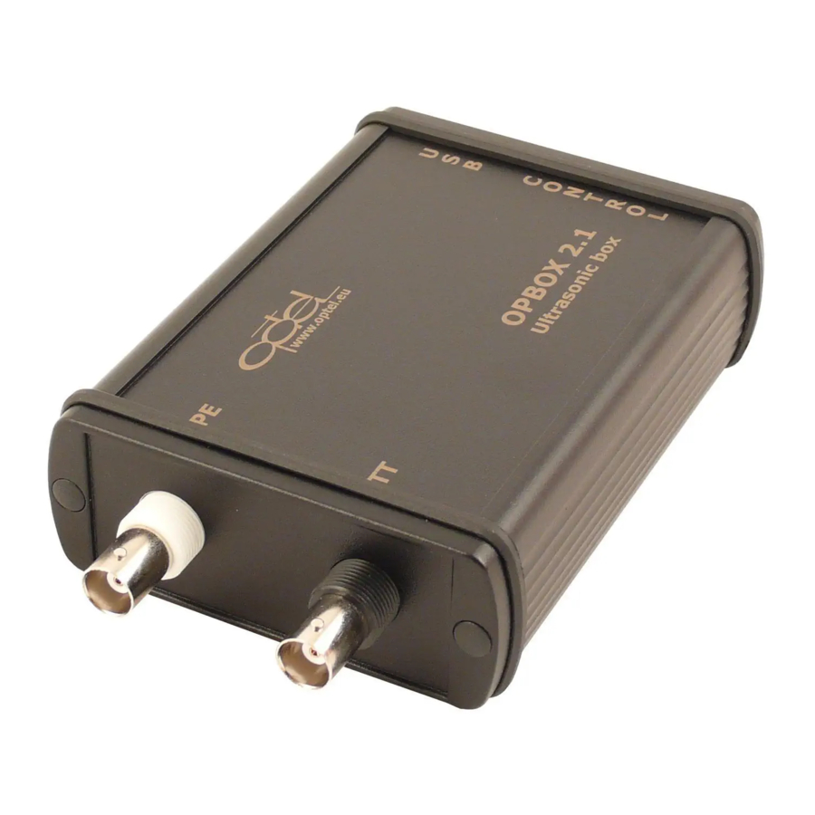
Miniature ultrasonic data acquisition system with integrated
Valid for hardware with firmware: Rev. 2.1.60
Document version:
Date of creation:
OPBOX ver 2.1
pulser&receiver
Description and manual
1v3
2016-08-08
Przedsiębiorstwo Badawczo-Produkcyjne
tel.: +48 (071) 329 68 54
fax.: +48 (071) 329 68 52
e-mail: optel@optel.pl
OPTEL Sp. z o.o.
ul. Morelowskiego 30
PL-52-429 Wrocław
http://www.optel.pl
Wrocław
Advertisement
Table of Contents

Summary of Contents for optel OPBOX-2.1
- Page 1 Przedsiębiorstwo Badawczo-Produkcyjne OPTEL Sp. z o.o. ul. Morelowskiego 30 PL-52-429 Wrocław tel.: +48 (071) 329 68 54 fax.: +48 (071) 329 68 52 e-mail: optel@optel.pl http://www.optel.pl Wrocław OPBOX ver 2.1 Miniature ultrasonic data acquisition system with integrated pulser&receiver Description and manual Valid for hardware with firmware: Rev.
-
Page 2: Table Of Contents
Content 1.Technical parameter.....................3 2.List of commands and control registers................5 3.Starting the work with the device..................6 4.Introduction to data acquisition settings.................6 4.1.Basic features of acquisition in FIFO mode:..............6 5.Meanings of basic acquisition elements................7 The description of acquisition in FIFO more requires the definition of some basic elements and assumptions. -
Page 3: Technical Parameter
1. Technical parameter Parameter of analogue receiver: Adjustable amplifier: -31dB to 65dB (step 0.5dB) Switchable preamplifier: +24dB Switchable attenuator: -20dB Input voltage: ± 275mV; ± 2.0V with attenuator -20dB. Bandwidth: 0.5 MHz - 25 MHz (-3dB) Switchable hardware filters (-3dB): 0.5 - 6MHz, 0.5 - 10MHz, 0.5 - 15MHz,... - Page 4 Position counter 32-bit; Special functions Programmable input modes: 1X, 2X, 4X; Programmable triggering on position; Storing of position after triggering. Transducer connectors: PE (sending&receiving) BNC or Lemo; TT (only receiving) BNC or Lemo. CONTROL connector: Type: DB15 female DB15 pin Description Standard Description...
-
Page 5: List Of Commands And Control Registers
2. List of commands and control registers OPBOX-2.1 is controlled via USB-2.0 with the help of direct commands and a set of control registers. Direct commands: Name Vendor Request OPBOX_SN (0xD0) RESET (0xD1) RESET_FIFO (0xD2) DIRECT_SW_TRIG (0xD3) DIRECT_ACK (0xD4) DIRECT_DATA_READY... -
Page 6: Starting The Work With The Device
3. Starting the work with the device OPBOX-2.1 is powered from USB interface and is conform with USB2.0 standard. According to its requirements there are some limits, concerning power supply (max. start current, max. continuous power). To fulfill this standard requirements OPBOX 2.1 has three independent power supply branches (analogue part, 12V part and ADC/DAC converters part). -
Page 7: Meanings Of Basic Acquisition Elements
header and remaining part is created by the signal data coming from the ADC; The header contains actual information about the given measurement, such as: – measurement index, encoder position in the moment of trigger, the results of hardware peak and transition detectors, etc. The settings of signal acquisition mechanism allow to adapt flexible buffering according –... - Page 8 Elements defined above are shown on the following picture. Header Acquisition Data Header Acquisition Data Header Acquisition Data HEADER_SIZE DEPTH 54 bytes 1..262090 bytes Frame FRAME_SIZE = HEADER_SIZE + DEPTH Packet PACKET_LENGTH = 3 Frames Figure 5.1: Data organization in Header and Packets Header Header Header...
-
Page 9: Header Of Acquisition Frame
6. Header of Acquisition Frame Acquisition header has 54 bytes, described in details with the following table: Register Value Byte No Name Description address range Start of Frame '@' (0x40) Beginning character of frame/header ASCII „@” FrameIdx 0x06 [7:0] Actual value of frame counter – 16-bit counter with [15:8] automatic reset at overflow TimeStamp... -
Page 10: Configuration And Maintenance Of Acquisition In Real Time
7. Configuration and maintenance of acquisition in real time Configuration and maintenance of acquisition in real time should be made according to the following schematic: 1. Stop of acquisition, that is going on: blocking all trigger sources (bit TriggerEnable in TRIGGER register). - Page 11 - receiving all packets until the moment as the flag PACKET_READY will have zero value. - the device buffer can contain a fragmentary acquisition packet (not the whole PACKET_LEN), the amount of remaining frames should be read from the register FRAME_CNT;...
-
Page 12: Comments To The Acquisition Settings
(reading of different length of Frame/Packet as stored in the buffer). This is the reason, why the memory controller in OPBOX-2.1 automatically detects and reacts to such situations, to avoid reading errors during changes of critical parameter settings. The description of behavior of OPBOX-2.1 during changes of DEPTH and... -
Page 13: Change Of The Measurement Window Setting (Depth)
8.3.1. Change of the measurement window setting (DEPTH) Changing of DEPTH setting causes that it is necessary to calculate new parameters of acquisition buffering (PACKET_LEN_MAX, placing of frames in relation to memory of TGC curve, etc.). Changing DEPTH parameter automatically changes the packet length too. -
Page 14: Resetting Of Acquisition Buffer
OPBOX-2.1 has a power control system fulfilling the needs of USB-2.0 interface specification and to secure the system for the case of overload of power supply. - Page 15 0x3FFFF FRAME_SIZE Frame N TGC[DEPTH-1] N = PACKET_LEN_MAX TGC[DEPTH-2] DEPTH Memory (256kB) TGC[3] TGC[2] TGC[1] Frame 3 TGC[0] Frame 2 HEADER_SIZE = 54 54x TGC[0] Frame 1 (recommended) 0x00000 Figure 8.1: Organization of TGC curves in the Table of Amplification Curves The sending of amplification curves to the device should always include the transfer of the whole 256kB table of data, needed to write the whole TGC curves buffer.
-
Page 16: Maintenance Of Peak Detectors Modules
9. Maintenance of Peak Detectors modules OPBOX 2.1 has three hardware peak and level detector modules – gates PDA, PDB i PDC. They have following parameters: three independent gates with peak detectors and level comparators; – configurable start and stop point for each gate; –... -
Page 17: Maintenance Of The Incremental Encoders Modules
10. Maintenance of the incremental encoders modules OPBOX 2.1 has two encoder counters modules ENC1 and ENC2 that are independent able to work with two incremental encoders having quadrature inputs CHA and CHB and index input IDX. Parameters of encoder modules: two independent position counters;...
Need help?
Do you have a question about the OPBOX-2.1 and is the answer not in the manual?
Questions and answers