Table of Contents
Advertisement
Quick Links
Advertisement
Table of Contents

Summary of Contents for Minuteman SNMP-SSL
- Page 1 SNMP-SSL UPS SNMP Card (Web-Based monitoring SNMP Card) User’s Manual...
-
Page 2: Table Of Contents
Hardware Installation ....................6 Configuration trough the Serial Port................7 Configuration through Telnet ..................17 Configuration through a Web Browser ................18 Chapter 3 Managing the SNMP-SSL/UPS via Web Browser ......... 21 UPS Monitoring ......................21 Comprehensive View ....................21 Help Menu........................22 UPS Identification...................... -
Page 3: Electronic Emission Notice
All the service of this equipment must be perform by qualified service personnel. Remove rings, watches and other jewelry before servicing the unit. Before plugging in or pulling out the SNMP-SSL card to and/or from the UPS, please make sure that the UPS is in the OFF position. -
Page 4: Chapter 1 Introduction
• Remote UPS monitoring via SNMP, HTTP and JAVA applets Allows monitoring of the UPS using SNMP-SSL card’s MIB (Management Information Base) files - provided with SNMP-SSL card, Internet Browser or Java monitoring applets. • Configure UPS and SNMP-SSL card’s functions from any client (password protected) Set UPS and SNMP-SSL card’s parameters from any SNMP management station or... -
Page 5: Package Contents
SNMP-SSL card is an interface between UPS and the network. It can obtain the status from a UPS and issue commands to it. SNMP-SSL card supports two kinds of protocol – SNMP and HTTP for user access. Through the SNMP NMS and Web Browser, user can obtain the UPS status, issue commands to UPS and setting up the SNMP-SSL card through the network. -
Page 6: Chapter 2 Installation
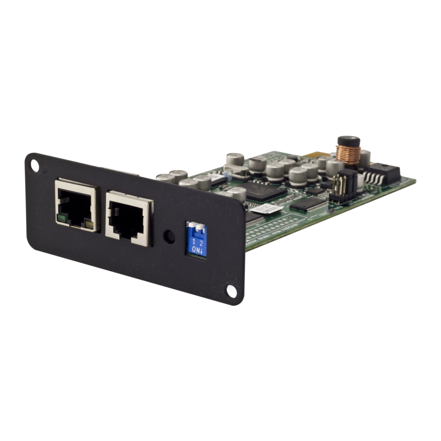
3. Set up via Web Browser Hardware Installation Note: The SNMP-SSL cards are designed to be Hot Swappable, but there is a remote chance that when Hot-Swapping the SNMP-SSL card that the UPS will shutdown. MINUTEMAN recommends following steps 1 through 4 when installing the SNMP-SSL card, but to hot-swap, skip to step number 3. -
Page 7: Configuration Trough The Serial Port
SNMP-SSL Configuration through the Serial Port 1. Use the RJ45 to RS232 serial cable to connect between the SNMP-SSL card’s COM port and the COM port on the workstation. 2. Set both the DIP-switches of the SNMP-SSL card to the OFF position (operating mode) for configuration. - Page 8 SNMP-SSL 4. Enter a name and choose an icon for the connection and then click OK. Figure 2-4: New HyperTerminal connection Select direct COM port connection. Select the appropriate COM port and then click Figure 2-5: Select Direct to COM port connection...
- Page 9 Figure 2-6: Setup of the COM port parameters 7. Power on the UPS and wait for SNMP-SSL card to boot up. Hit the “Enter” key once to display the menu below. Enter the password (default password is admin) and hit the “Enter”...
- Page 10 SNMP-SSL 8. The SNMP-SSL Configuration Utility Main Menu will be displayed. Select “1” to enter the SNMP-SSL Configuration Menu. Figure 2-8: SNMP-SSL Configuration Utility Main Menu 9. The SNMP-SSL Configuration Menu will be displayed. Select “1” to enter the System Group Configuration Menu.
- Page 11 Note: The minimum requirement is to set the IP Address (The default IP address is 192.168.1.100), the Gateway Address, and the Network Mask to be able to connect to the SNMP-SSL card with a Web Browser. All other setting may be configured using a Web Browser except for changing the Login Password.
- Page 12 Figure 2-12: SNMP-SSL Control Group Configuration Menu After completing these settings, select “0” to return to the Configuration Menu. 13. In the Configuration Menu select “3” to configure the SNMP-SSL parameters. Figure 2-13: Parameter Group Configuration Menu After completing these settings, select “0” to return to the Configuration Menu.
- Page 13 SNMP-SSL 14. In the Configuration Menu, select “4” to configure the Email settings. Figure 2-14: Email Group Configuration Menu After completing these settings, select “0” to return to the Configuration Menu. 15. In the Configuration Menu, select “5” to configure the Web Authentication Group settings.
- Page 14 17. In the Configuration Menu, select “6” to configure the Ping Group settings. Figure 2-17: Ping Group Configuration Menu After completing these settings, select “0” to return to the Configuration Menu and then select “0” again to return to the SNMP-SSL Configuration Utility Main Menu.
- Page 15 SNMP-SSL 18. In the SNMP-SSL Configuration Utility Main Menu, select “3” to configure the Access Control settings. To set up more restrictive access, you can use the access table to add the IP address of the PC’s on which you wish to modify the access permissions.
- Page 16 20. In the SNMP-SSL Configuration Utility Main Menu, select “5” to configure the Trap Receiver settings. If you want to use a PC to perform the SNMP manager ‘trap’ function in order to manage UPS through SNMP-SSL card, the IP address of the PC must be added to the SNMP-SSL list.
-
Page 17: Configuration Through Telnet
Disconnect the RJ45 to RS232 serial cable from the SNMP-SSL card’s COM port and the computer COM port. Connect the network cable to the Network port on the SNMP-SSL card. Open a Web Browser and input the IP address to view the SNMP-SSL card’s web pages. -
Page 18: Configuration Through A Web Browser
Normally, the first time you use SNMP-SSL card, your workstation is unable to communicate to SNMP-SSL card since they are not in the same IP subnet. However, you may use the “route add” command to manipulate the network routing table in your workstation in order to complete the SNMP-SSL card’s configuration. - Page 19 5. Open the SNMP-SSL Management folder. 6. Open the SNMP-SSL Configuration page. 7. Click the Become Administrator button at the bottom of the page. Enter SNMP-SSL as the login name and admin as the password. (Case sensitive) 8. Enter the IP Address.
- Page 20 12. Open the Date and Time page. 13. Enter the correct date and time information. 14. When finished click Set Value to save the settings. Figure 2-24 SNMP-SSL Date and Time page 15. Open the SNMP-SSL Control page. 16. Make the appropriate changes.
-
Page 21: Chapter 3 Managing The Snmp-Ssl/Ups Via Web Browser
SNMP-SSL Chapter 3 Managing the SNMP-SSL/UPS via Web Browser This chapter describes how to use the Web-based interface to monitor the SNMP-SSL card. 1. Start your Web Browser and enter the IP address 2. The home page will be displayed. -
Page 22: Help Menu
Select the Help icon located at the bottom of each page for a detail description of each item. Figure 3-2 SNMP-SSL Help Menu UPS Identification Select the UPS Identification from the UPS Monitoring menu of the home page to get the UPS and SNMP-SSL card’s Identification parameters. Figure 3-3 SNMP-SSL UPS Identification... -
Page 23: Battery Parameters
Select the Battery Parameters from the UPS Monitoring on the main menu to get the UPS’s battery parameters. Figure 3-4 SNMP-SSL Battery Parameters Input Parameters Select Input Parameters from the UPS Monitoring on the main menu to get the UPS’s input parameters. -
Page 24: Output Parameters
Select Output Parameters from the UPS Monitoring on the main menu to get the UPS’s output parameters. Figure 3-6 SNMP-SSL Output Parameters Alarm Table Select Alarm Table from the UPS Monitoring on the main menu to get the status of the UPS’s alarms. -
Page 25: Client Table
SNMP-SSL Client Table Select Client Table from the UPS Monitoring on the main menu to get a list of the connected clients, which are running the shutdown software. Figure 3-8 SNMP-SSL Client Table... -
Page 26: Chapter 4 Ups Management
RS232 or Telnet) or the SNMP/HTTP Access Control (via Web Browser) in the SNMP-SSL card, you can only view the UPS status; it will not be able to perform any configuration on SNMP-SSL/UPS. (See the Access Control Table Setting and the SNMP/HTTP Access Control for details.) -
Page 27: Ups Control
1. Quick Battery Test (Test the battery for 10-seconds) 2. Test Until Battery Low (test the UPS until a Low Battery Warning occurs, then resets to the AC mode). 3. Set Value: Saves the settings. Figure 4-3 SNMP-SSL UPS Battery Test... -
Page 28: Ups Battery Test Schedule
1. Quick Battery Test - Test the battery for 10-seconds 2. Test Until Battery Low - Test the UPS until a Low Battery Warning occurs, then resets to the AC mode. 3. Set Value: Saves the settings. Figure 4-4 SNMP-SSL UPS Battery Test Schedule... -
Page 29: Ups Shutdown
8. EMD Alarm-1: Alarm-1 sensor detects an active alarm. 9. EMD Alarm-2: Alarm-2 sensor detects an active alarm. When a shutdown event has occurred, SNMP-SSL card will take the selected action as define in the Shutdown Actions column. Available actions are: a. -
Page 30: Weekly Schedule
Figure 4-6 SNMP-SSL Weekly Schedule Special Day Schedule This menu allows you to modify the parameters of the shutdown/restore events associated with certain days of the year. When finished click Set Value to save the settings. Figure 4-7 SNMP-SSL Special Day Schedule... -
Page 31: Emd Configuration
5. EMD Status: The EMD can be configured as 'Disabled' or 'Auto'. The setup should be configured as 'Disabled' if an EMD is not attached to the port. The EMD type will be auto detected by the SNMP-SSL card if configured as 'Auto' and if the EMD is plugged into the port. -
Page 32: Chapter 5 Snmp-Ssl Management
SNMP-SSL Chapter 5 SNMP-SSL Management The following menus allow the user to configure the SNMP-SSL control parameters. All the menus are available for all users in the read-only mode, except for the administrator, which has access in the read/write mode. - Page 33 9. Battery Replacement Date Type: The default type is UPS. When the SNMP-SSL card is installed in the UPS, the SNMP-SSL card will poll the UPS for this information. At the end of the batteries useful service life and battery replacement has been performed, the user can input the new dates for the Last and Next Battery Replacement Dates.
-
Page 34: Snmp-Ssl Control
SNMP-SSL Control This menu allows you to enable or disable the communication protocols available in the SNMP-SSL card. Some of the items in this menu are only configurable to those having read/write access rights. 1. BOOTP/DCHP Status: Enabling or disabling the Boot Protocol (BOOTP) / Dynamic Host Configuration Protocol (DHCP). -
Page 35: Snmp-Ssl Upgrade
SNMP-SSL SNMP-SSL Upgrade This menu allows the Administrator to flash upgrade the SNMP-SSL card’s firmware. 1. Browse: Searches for the location where the firmware file (Bin) is stored. 2. Upgrade Agent Firmware: Starts the upgrade process. 3. Upload Status: Shows the status of the upgrade process. -
Page 36: Snmp-Ssl Radius Configuration
5. Share Secret of Secondary Server: Set the Share Secret of Secondary Server. 6. Packet Timeout Interval (sec): Set the Packet Timeout Interval. 7. Packet Retry Times: Set the Packet Retry Times. 8. Set Value: Saves the settings. Figure 5-5 SNMP-SSL RADUIS Configuration... -
Page 37: Snmp-Ssl Change Trap Level
1. Index: The index number of the entry in the table. 2. Trap Name: The short description of each Trap. 3. Trap Level: There are three levels that can be selected by the users: a. Severe b. Warning c. Informational Figure 5-6 SNMP-SSL Change Trap Level... -
Page 38: Snmp/Http Access Control
SNMP-SSL SNMP/HTTP Access Control This menu allows the administrator to configure the SNMP/HTTP Access Control to enable specific workstations for read/write access to the SNMP-SSL card. See Appendix B HTTP Security Control. NMS Table: 1. Index: The index number of the entry in the table. -
Page 39: Snmpv3 Usm Table
SNMP-SSL SNMPv3 USM Table This menu allows the administrator to configure the SNMP-SSL card for the SNMPv3 USM (User Security Model). SNMPv3 USM provides confidentiality and integrity for network management communications. SNMPv3 USM also allows for user-based authentication and access control. Rather than using the two-level “read” and “write”... -
Page 40: Snmp Trap Receivers
SNMP-SSL SNMP TRAP Receivers This menu allows the administrator to configure the SNMP-SSL card to send SNMP Traps to eight different Network Management Stations (NMS). The MIB files must be installed on the NMS. 1. Index: The index number of the entry in the table. -
Page 41: Wakeonlan Targets
SNMP-SSL WakeOnLAN Targets WOL" function allows you to start up client PCs through the network. 32 clients can be set up. After the client shuts down because of the UPS shutdown events, the WOL packet will be sent to client to wake up the PC. -
Page 42: Homepage Refresh Rate
SNMP-SSL Homepage Refresh Rate This menu allows the administrator to set the refresh rate of the SNMP-SSL card’s web pages. When finished click Set Value to save the settings. Figure 5-11 Homepage Refresh rate Email Notification This menu allows the administrator to configure the email setting to receive notifications and/or reports from SNMP-SSL card by email once an event has occurred. - Page 43 SNMP-SSL 11. Mail Type: This column is for selecting what type of email is sent to a specific Mail Receiver. The choices are: a. None: Allows you to disable sending emails to a specific recipient. b. Events: When a specific event occurs the designated recipient will receive an email.
-
Page 44: External Links
External Links This menu allows you to set up the External Links. Each index can be linked to an external web page such as another UPS with an SNMP-SSL card, or a technical support homepage. 1. Screen Text: This is the description of the hyperlink name, which will be displayed on the menu tree. -
Page 45: Chapter 6 History And Events Logs
The following menus allow you to capture (save in .csv format) and view History and Event logs for the UPS and Event logs for the SNMP-SSL card. These log files are very useful when diagnosing power and network problems. Note: To Save or Clear the log files go to the Clear &... -
Page 46: Ups Extended Log Data
UPS parameters, minimum, maximum and the average values are shown in each of the records. The Administrator can change the time interval in the SNMP-SSL Configuration page. The existing values are overwritten when the maximum number of entries (rows) has been reached. -
Page 47: Ups Events Log Data
SNMP-SSL UPS Events Log Data This menu lists all the UPS events that have occurred since the table was last cleared. The existing values are overwritten when the maximum number of entries (rows) has been reached. The Administrator has the access right to delete the entries of the table. -
Page 48: Snmp-Ssl Events Log Data
SNMP-SSL SNMP-SSL Events Log Data This menu lists all the SNMP-SSL card’s events that have occurred since the table was last cleared. The existing values are overwritten when the maximum number of entries (rows) has been reached. The Administrator has the access right to delete the entries of the table. -
Page 49: Clear & Save Log Data
SNMP-SSL Clear & Save Log Data This page menu allows the Administrator to Save or Clear the Log files. The Log files are saved in .csv format, which can be read in Excel. 1. Clear Log Data: The Administrator can clear a specific Log file by checking the box next to the Log file that you want to Clear and then click the Clear button. -
Page 50: Chapter 7 Monitoring Snmp-Ssl/Ups Via Java Applet
SNMP-SSL Chapter 7 Monitoring SNMP-SSL/UPS via Java Applet SNMP-SSL card provides three real-time graphical user interfaces written in Java Applet to monitor the UPS in LAN or WAN. Java monitor: Displays the UPS’s key parameters. UPS History Log monitor: Displays the UPS’s History Log. -
Page 51: Status Bar
The status bar displays the current status of the UPS. The green color represent that the UPS is in the normal condition. If SNMP-SSL card receives a status change of the UPS, for example an AC failure, the AC OK box will then change to a red color and display AC fail representing that the UPS has lost utility power. -
Page 52: Ups History Log
UPS History Log By clicking the Log button at the top right-hand side of the SNMP-SSL card’s Home Page, a UPS History Log will be opened in a separate window. This applet displays the UPS History Log in a line graph format. You can select any combination of the parameters to be displayed on the graph by checking the check box beside each parameter and then click the Refresh button. -
Page 53: Ups Extended History Log
UPS Extended History Log By clicking the Java button at the top right-hand side of the SNMP-SSL card’s Home Page, a UPS Extended History Log will be opened in a separate window. This applet displays the UPS History Log in a line graph format. You can select any combination of the parameters to be displayed on the graph by checking the check box beside each parameter and then click the Refresh button. -
Page 54: Extra Browsing Options Pda & Wap
SNMP-SSL Extra Browsing Options PDA & WAP SNMP-SSL now provide more easy of using remote browsing ways. User can get the UPS status through PDA or WAP mobile phone, which own ability to connect to Internet already. According to every manufacturer setting was different, please reference to PDA and WAP User Manual for connect to Internet. -
Page 55: Chapter 8 Managing Snmp-Ssl/Ups Via Snmp
(via Serial Port or Telnet) or the SNMP/HTTP Access Control (via Web Browser) in the SNMP-SSL card, the SNMP NMS can only view the UPS status; it will not be able to perform any configuration on SNMP-SSL/UPS. (See Pg. 15 Access Control Table Setting and Pg. -
Page 56: Chapter 9 Shutdown Software
2. Run the “SD_SNMP-SSL Service_4.20.exe” program on the CD-ROM. 3. A dialog box will be on the screen, type in the IP address of designated SNMP-SSL card, its client name and shutdown delay time. Click the Def. Button if you choose the client name as the workstation you are working on. -
Page 57: View The Connected Client From A Web Browser
SNMP-SSL View the Connected Client from a Web Browser 1. Open a Web Browser and input the IP address of the SNMP-SSL card. 2. Select the Client Table from the UPS Monitoring folder. A list of the connected devices will be shown on the screen. -
Page 58: Shutdown Process In Windows
SNMP-SSL Shutdown Process in Windows When the SNMP-SSL card detects a power event it will send the shutdown command to its connected clients. A pop-up dialog box will notify the client that the system will be shutdown. The user can select "Shutdown Now" to start the shutdown process or "Close"... -
Page 59: Installing The Shutdown Software In Sco Openserver Unix
Installing the Shutdown Software in SCO OpenServer UNIX 1. From a workstation running SCO OpenServer login as a supervisor. 2. Insert the SNMP-SSL CD-ROM into the CD-ROM drive. 3. If you have already mounted the CD-ROM drive, skip to step 5 4. - Page 60 SNMP-SSL ;Sample configuration file of uGuard ;RemoteHostIP: The IP address of remote UPS. ;Set the address to default IP (0.0.0.0) if no SNMP-SSL Service is connected. RemoteHostIP = 0.0.0.0 ;ClientName:The name of the this machine[optional]. Free form for this parameter.
-
Page 61: Uguard Parameters Description
SNMP-SSL uGuard Parameters Description To run or view the uGuard parameters, use the following command: # cd /uGuard # uGuard -h Figure 9-5 uGuard Parameters Description. Deleting uGuard 1. Unload uGuard #cd /etc #uGuard -U 2. Remove uGuard files #cd /etc #rm uGuard #rm uGuard.conf... -
Page 62: Installing The Shutdown Software In Linux Kernel 2.0.X
SNMP-SSL Installing the Shutdown Software in Linux kernel 2.0.x The shutdown software supplied from the SNMP-SSL CD-ROM for the Linux can be install on the Linux operating system with kernel version higher than 2.0.x. To be able to execute the shutdown program correctly, please check the following procedures: 1. -
Page 63: Installing The Shutdown Software In Solaris
SNMP-SSL Installing the Shutdown Software in Solaris 1. From a workstation running Solaris and login as an administrator. 2. Insert the SNMP-SSL CD-ROM into the CD-ROM drive. 3. Mount CD-ROM 4. Create new directory. (mkdir uGuard) 5. Copy the shutdown programs into the directory. Then extract the programs to the directory of ./uGuard, and then uncompress it. -
Page 64: Uguard Command Descriptions
SNMP-SSL 8. Type “y” (yes) to start the shutdown daemon. uGuard Command Descriptions... - Page 65 SNMP-SSL 1. Execute “uGuard –d” command to suspend shutdown daemon. 2. Execute “uGuard –r” command to resume shutdown daemon. 3. Execute “uGuard –p” command to probe the shutdown daemon status.
-
Page 66: Appendix A Snmp-Ssl Upgrade Utility Software
To be able to perform firmware upgrading, SNMP-SSL card must be connected to the same network as the workstation from which the file is to be sent. In the SNMP-SSL Control menu, check that the Network Upgrade is enabled and that you have the login string information and the Community Read/Write Password. -
Page 67: Updating The Snmp-Ssl Card's Firmware Form Unix
Updating the SNMP-SSL card’s Firmware from UNIX To be able to upgrade the firmware using a UNIX operating system, you must have the command tftp installed in your system. To upgrade the firmware of the SNMP-SSL card, execute the following command line: # tftp tftp> binary tftp>... -
Page 68: Appendix B Http Security Control
SNMP-SSL Appendix B HTTP Security Control... -
Page 69: Appendix C Technical Information
Real time clock Network Protocol SNMP over UDP/IP HTTP over TCP/IP ARP, TFTP, SSH, SSL, NTP and ICMP Supported MIB UPS MIB (RFC1628) SNMP-SSL MIB Operating 0 ~ 40° C Temperature Operating Humidity 10 ~ 80 % Power Input 8-15V DC Power Consumption 3.0 Watts Maximum... -
Page 70: Obtaining Technical Assistance
SNMP-SSL Obtaining Technical Assistance For Technical Support on the Web, please visit the Support section of our Web site or visit our online Discussion Forum. In order to diagnose the problem you are having, our technicians need the following information from you. -
Page 71: Limited Product Warranty
SNMP-SSL Limited Product Warranty Para Systems Inc. (Para Systems) warrants this equipment, when properly applied and operated within specified conditions, against faulty materials or workmanship for a period of three years from the date of original purchase by the end user. For equipment sites within the United States and Canada, this warranty covers repair or replacement of defective equipment at the discretion of Para Systems.