Advertisement
Table of Contents
Advertisement
Table of Contents

Subscribe to Our Youtube Channel
Summary of Contents for Ruijie FE-SFP-LX-MM1310
- Page 1 Ruijie Transceiver Modules Installation and Reference Guide V3.0...
- Page 2 This document is provided “as is”. The contents of this document are subject to change without any notice. Please obtain the latest information through the Ruijie Networks website. Ruijie Networks endeavors to ensure content accuracy and will not shoulder any responsibility for losses and damages caused due to content omissions, inaccuracies or errors.
- Page 3 It is intended for the users who have some experience in installing and maintaining network hardware. At the same time, it is assumed that the users are already familiar with the related terms and concepts. Obtaining Technical Assistance Ruijie Networks Website: http://www.ruijienetworks.com/ Service Email: service_rj@ruijienetworks.com ...
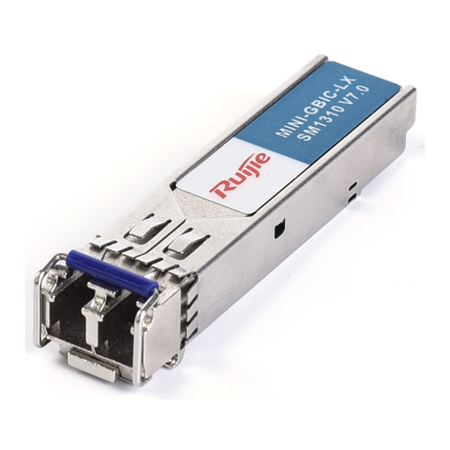
- Page 4 Installation and Reference Guide Mini-GBIC and SFP Modules Mini-GBIC and SFP Modules Overview The SFP (Small Form-Factor Pluggable) transceiver modules are classified into two models: optical SFP modules including duplex SFP modules shown in Figure 1-1 and BIDI SFP modules in Figure 1-2, and copper SFP modules in Figure 1-3.
- Page 5 The schematic diagrams are for your reference only. The product appearance is subject to the actual model. Models and Specifications Table 1-1 Existing Models of the Optical SFP Module. Rate Standard SFP Product Model FE-SFP-LX-MM1310 FE-SFP-LX-MM1310-SGMII FE-SFP-LH15-SM1310 Ethernet Long wavelength / long distance FE-eSFP-LH15-SM1310...
- Page 6 1000Base-T GE-SFP-GT The types/models of MINI-GBIC and SFP modules are being updated. If more accurate models of the module are required, please contact Ruijie marketing staff or technical support engineers. Table 1-3 Pairing Models of the SFP BIDI Module Rate/Distance...
- Page 7 Table 1-6 Models and Technical Specifications of the SFP Module Intensity Intensity Optical Wavelength Transmitted Light Received Light / SFP Model Fiber / dBm (nm) (Yes/No) Type FE-SFP-LX-MM1310 1310 FE-SFP-LX-MM1310-SGMII 1310 FE-SFP-LH15-SM1310 1310 FE-SFP-LH20-SM1310-SGMII 1310 FE-SFP-LX20-SM1310-BIDI 1310TX/1550RX FE-SFP-LX20-SM1550-BIDI 1550TX/1310RX FE-eSFP-LH15-SM1310...
-
Page 8: Table Of Contents
To keep the optical module clean, please make sure that the dust cap is mounted when it is not connected to a fiber cable. The SFP module does not support auto-negotiation to 100Mbps. Table 1-7 Module Cabling Specifications Connector Optical Fiber Core Specification Maximum Cabling SFP Model Type Type (um) Distance FE-SFP-LX-MM1310 62.5/125... -
Page 9: Mini-Gbic-Zx50-Sm1550
Installation and Reference Guide Mini-GBIC and SFP Modules FE-SFP-LX-MM1310-SGMII 62.5/125 FE-SFP-LH15-SM1310 9/125 15km FE-SFP-LH20-SM1310-SGMII 9/125 20km FE-SFP-LX20-SM1310-BIDI 9/125 20km FE-SFP-LX20-SM1550-BIDI 9/125 20km FE-eSFP-LH15-SM1310 9/125 15km MINI-GBIC-SX-MM850 50/125 500m SFP-MM850 50/125 500m GE-SX-MM850 50/125 500m 62.5/125 275m GE-eSFP-SX-MM850 50/125 550m GE-eSFP-LX-SM1310... - Page 10 Installation and Reference Guide Mini-GBIC and SFP Modules Wavelength means the optical wave band for transmission of light signal. Currently, the commonly used XFP optical modules have three centre wavelengths: 850 nm, 1310 nm and 1550 nm. Usually, the wave band of 850 nm is for short-distance transmission and the wave bands of 1310 nm and 1550 nm are for long-distance transmission.
- Page 11 Installation and Reference Guide Mini-GBIC and SFP Modules Intensity of Received Light Intensity of received light refers to the optical input power received by the optical module. The unit is dBm. If the actual received light intensity is less than the minimum value, the module may fail in connection or lose many frames. If the actual received light intensity is greater than the maximum value, the module may be damaged.
- Page 12 Installation and Reference Guide Mini-GBIC and SFP Modules 4. If the optical fiber jumper is correctly connected, check whether the connected SFP modules are properly matched. 5. Precautions during installing: The optical module cannot be inserted inversely. If the optical module cannot be inserted to the end along one direction, do not forcibly to push it in and please try another direction.
-
Page 13: Mmf Yes
10G XFP Modules Overview Ruijie Networks provides the following 10G XFP transceiver modules: 10GBASE-SR-XFP. The 10G XFP transceiver is an input/output device that supports hot swapping. When installed into the 10G Ethernet XFP port or slot, the 10G XFP transceiver is responsible for connecting the port and optical fiber network. The appearance of XFP module is shown in Figure 2-1. - Page 14 Installation and Reference Guide 10G XFP Modules 200(OM1) 62.5 /125 10GBASE-SR-XFP 2000(OM3) 300m 50/125 500(OM2) 400(OM1) Module Specifications Wavelength Wavelength means the wave band for transmission of light signal. Currently, the commonly used XFP optical modules have three centre wavelengths: 850 nm, 1310 nm and 1550 nm. Usually, the wave band of 850 nm is for short-distance transmission and the wave bands of 1310 nm and 1550 nm are for long-distance transmission.
- Page 15 Installation and Reference Guide 10G XFP Modules Digital Diagnostic Monitor (DDM) is widely used in optical modules to dynamically measure the temperature, intensity of transmitted and received light, voltage, and laser bias current of the module. You can run commands to get the monitoring result in the host system that supports display of DDM information.
- Page 16 Installation and Reference Guide 10G XFP Modules Installing the XFP Module 1. Reveal the handle of the XFP module to lock against the snap on top of the module, and pinch the both sides of the XFP module to push it levelly and slowly into the optical module slot until the optical module firmly connects to the slot (there would be a click sound if the optical module is correctly connected to the slot), as shown in Figure 2-5: Figure 2-5 Installing the XFP Optical Module 2 When you connect the XFP module to the optical fiber network, use the optical fiber jumper.
- Page 17 Installation and Reference Guide 10G XFP Modules Precautions for removing Please pull out the optical fiber before removing the optical module. Please do not forcibly pull out the module without pulling down the handle of the optical module first so as not to cause any damage.
- Page 18 10G SFP+ Modules Overview The 10G SFP+ transceiver module of Ruijie Networks is composed of an SFP+ optical module, an SFP+ copper cable module or an SFP+ AOC cable, as shown in Figure 3-1 and Figure 3-2. The XG-SFP-SR-MM850, XG-SFP-LR-SM1310, XG-SFP-ER-SM1550 and XG-SFP-ZR-SM1550 are optical modules.
-
Page 19: Smf
Installation and Reference Guide 10G SFP+ Modules The schematic diagrams are for your reference only. The product appearance is subject to the actual model. Models and Technical Specifications Table 3-1 SFP+ Optical Module Intensity Optical Intensity of Received Wavelength Transmitted Model Fiber Light/dBm... - Page 20 Installation and Reference Guide 10G SFP+ Modules Do not use short-distance optical fiber connection for the XG-SFP-ER-SM1550 and XG-SFP-ZR-SM1550 to avoid overloading on the optical transceiver. If the optical power of the module receiver end is greater than or equal to -1 dBm, install an attenuator at the receiver end so that the optical power can be less than -1 dBm. The optical module is a laser device.
- Page 21 The types/models of the SFP+ modules are being updated. If more accurate models of the module are required, please contact Ruijie marketing staff or technical support engineers. Additional connecting cables are not needed. You just need to plug the cable ends into the appropriate device ports for interconnection.
- Page 22 Installation and Reference Guide 10G SFP+ Modules A single-mode fiber (SMF) has a smaller core and can transmit one mode of light. Therefore, it has a lower modal dispersion and is applicable to remote communication. Connector Type Optical fibers are joined by optical fiber connectors to form fiber jumpers. A fiber jumper is connected to optical modules through an optical fiber connector, so that the optical channel is detachable for the convenience of debugging and maintenance of the optical system.
- Page 23 Installation and Reference Guide 10G SFP+ Modules the anti-static wrist strap around the wrist and tighten the lock; make sure that the anti-static wrist strap has a good contact with the skin and is well grounded. Wearing jack type anti-static wrist strap, for example, is as shown in Figure 3-6: Figure 3-6 Schematic Diagram for Wearing Jack Type Anti-static Wrist Strap Installing the 10G SFP+ Optical Module 1.
- Page 24 Installation and Reference Guide 10G SFP+ Modules Removing the 10G SFP+ Optical Module 1. Pull out the optical fiber line. 2. Pull the SFP + module handle downward to the horizontal position, gently pull the snap, and then pull out the SFP + module smoothly.
- Page 25 Installation and Reference Guide 10G SFP+ Modules The 10G SFP+ connector at the end of the copper cable cannot be inserted inversely. If the optical module cannot be inserted to the end along one direction, do not forcibly push it in and please try another direction. ...
- Page 26 25G SFP28 Modules Overview The 25G SFP28 transceiver module of Ruijie Networks is composed of an SFP28 optical module and an SFP28 AOC cable, as shown in Figure 4-1 and Figure 4-2. VG-SFP-SR-MM850 and VG-SFP-LR-SM1310 are optical modules. The VG-SFP-AOC1/3/5/7/10/20M are active copper cable modules. The 25G SFP transceiver is an input/output device that supports hot swapping.
- Page 27 Installation and Reference Guide 25G SFP28 Modules (nm) (Yes/No) Fiber Transmitted Light/dBm Type Light/dBm Rate VG-SFP-SR-MM850 (840,860) -8.4 -10.3 VG-SFP-LR-SM1310 (1295,1325) -4.5 -11.4 The transceiver module is a laser device. Please take care of your eyes and do not look into the laser beam directly.
- Page 28 The types/models of the SFP28 modules are being updated. If more accurate models of the module are required, please contact Ruijie marketing staff or technical support engineers. Additional connecting cables are not needed. You just need to plug the cable ends into the appropriate device ports for interconnection.
- Page 29 Installation and Reference Guide 25G SFP28 Modules Optical fibers are classified into two types: single-mode and multimode fibers according to the transmission mode of light in fibers. A multimode fiber (MMF) has a larger core and transmits light of various modes. But it has a higher modal dispersion. The modal dispersion grows with the increase of transmission distance.
- Page 30 Installation and Reference Guide 25G SFP28 Modules Module Installation Precautions Preparation before Installation Before installation, electron static discharge (ESD) protection is needed. To avoid damages to the electronic devices in the 25G SFP28 optical modules and 25G SFP28 cables caused by the static electricity generated during the installation, please wear the anti-static wrist strap around the wrist and tighten the lock;...
- Page 31 Installation and Reference Guide 25G SFP28 Modules It is recommended that before installing the fiber-optic lines, not remove the protecting rubber on the optical port of optical modules. It is recommended not insert the 25G SFP28 optical module with fiber optics directly into the slot. Please proceed with the installation after the optical fiber is pulled out.
- Page 32 Installation and Reference Guide 25G SFP28 Modules 2. After installing the plug of the copper cable module, connect the copper cable to the Ethernet network, and the switch port indicator “LINK/ACT” will be on; otherwise, check that the connector of the copper cable is correctly connected; Precautions during installing ...
- Page 33 Installation and Reference Guide 25G SFP28 Modules Precautions for removing When removing the 25G SFP28 copper cable, please pull the pull ring of the module levelly, otherwise it would result in the difficulty of pulling out the copper cable and even the damage to the module and slot. ...
- Page 34 40G QSFP+ Modules Overview The 40G QSFP+ transceiver module of Ruijie Networks is composed of a 40G QSFP+ module, copper cables and AOC cables, as shown in Figure 5-1, Figure 5-2 and Figure 5-3. The 40G QSFP+ module is hot-swappable input/output device that plugs into a 40-Gigabit Ethernet QSFP+ switch port through fiber or copper cables.
- Page 35 Installation and Reference Guide 40G QSFP+ Modules The schematic diagrams are for your reference only. Product appearance is subject to the actual model. Models and Technical Specifications Table 5-1 Models and Technical Specifications of 40G QSFP+ Modules Transmit Wavelength Receive (dbm) Models Fiber Type Supported...
- Page 36 Installation and Reference Guide 40G QSFP+ Modules (um) (MHz/km) (MPO 2000 100m(OM3) 40G-QSFP-SR-MM850 (840 ,860) connector) 4700 150m(OM4) 40G-QSFP-SR-MM850-BIDI (840 ,900) 2000 100m(OM3) connector) 4700 150m(OM4) 2000 300m(OM3) (MPO 40G-QSFP-LSR-MM850 (840 ,860) connector) 4700 400m(OM4) (1264.5,1277.5) (1284.5,1297.5) 40G-QSFP-LR4-SM1310 10km (1304.5,1317.5) connector) (1324.5,1337.5) (1264.5,1277.5)
- Page 37 Relative Humidity 10% to 90% The types/models of QSFP+ modules are being updated. If more accurate models of the module are required, please contact Ruijie marketing staff or technical support engineers. Module Specifications Wavelength Wavelength means the wave band for transmission of light signal.
- Page 38 Installation and Reference Guide 40G QSFP+ Modules A single-mode fiber (SMF) has a smaller core and can transmit one mode of light. Therefore, it has a lower modal dispersion and is applicable to remote communication. Connector Type Optical fibers are joined by optical fiber connectors to form fiber patch cord. A fiber patch cord is connected to optical modules through an optical fiber connector, so that the optical channel is detachable for the convenience of debugging and maintenance of optical system.
- Page 39 Installation and Reference Guide 40G QSFP+ Modules The 40G-QSFP-LR4-PSM-SM1310 module can be used with single-mode female MPO connectors only. The coupling end face of the MPO connectors is the angled physical contact (APC) patch cord, of which the core wires must be single-mode.
- Page 40 Installation and Reference Guide 40G QSFP+ Modules Figure 5-9 Dual-core LC Connector For devices supporting splitting 40G into 4 *10G, you can use MPO-4*LC fiber patch cords to convert 40G to 4 *10G. Figure 5-10 MPO-4*LC Fibers Digital Diagnostic Monitor (DDM) is widely used in optical modules to dynamically measure the temperature, intensity of transmitted and received light, voltage, and laser bias current of the module.
- Page 41 Installation and Reference Guide 40G QSFP+ Modules Installing the 40G QSFP+ Optical Module 1. For the snap-in module, reveal the handle of the QSFP + module to lock against the snap on top of the module, and use hand to pinch on both sides of the QSFP + module to push it levelly and slowly into the optical module slot until the optical module connects to the slot (there would be a click sound if the optical module is correctly connected to the slot).
- Page 42 Installation and Reference Guide 40G QSFP+ Modules 2. When you connect the 40G QSFP+ module to the optical fiber network, use the optical fiber patch cord. Based on the interface type of the Internet ports, choose the jumper with corresponding interfaces. 3..
- Page 43 Installation and Reference Guide 40G QSFP+ Modules Precautions for removing Please pull out the optical fiber before removing the optical module. Please do not forcibly pull out the module without pulling down the handle of the optical module first so as not to cause any damage.
- Page 44 Installation and Reference Guide 40G QSFP+ Modules 2.After installing the plug of the cable module, connect the cable to the Ethernet network, and the switch port indicator “LINK/ACT” will be on; otherwise, check that the connector of the cable is correctly connected; 3.
- Page 45 Installation and Reference Guide 40G QSFP+ Modules Removing the 40G QSFP+ Cable Module 40G QSFP+ cables include copper cables and AOC cables. 1. When pulling out the 40G QSFP+ cable module, you can hold the cable in the hand while pulling out the module pull ring levelly and then the module itself smoothly.
- Page 46 100G QSFP28 Modules Overview The 100G QSFP28 transceiver module of Ruijie Networks is composed of a 100G QSFP28 module , copper cables and AOC cables, as shown in Figure 6-1 and Figure 6-2. The 100G QSFP28 module is hot-swappable input/output device that plugs into a 100-Gigabit Ethernet QSFP28 switch port through fiber or copper cables.
- Page 47 Installation and Reference Guide 100G QSFP28 Modules (1294.53,1296.59) (1299.02,1301.09) 100G-QSFP-LR4-SM1310 -4.3 -10.6 (1303.54,1305.63) connector) (1308.09,1310.19) (1264.5-1277.5) (1284.5-1297.5) connector) 100G-QSFP-iLR4-SM1310 -6.5 -11.5 (1304.5-1317.5) (1324.5-1337.5) (1294.53,1296.59) (1299.02,1301.09) 100G-QSFP-ER4-SM1310 -2.5 -20.5 -3.5 (1303.54,1305.63) connector) (1308.09,1310.19 100G-QSFP-iLR4-PSM-S (1295,1325) (MPO/APC -5.5 -10.2 M1310 connector) MMF=Multimode fiber SMF=Single mode fiber Table 6-2 Cabling Specifications Core...
- Page 48 Installation and Reference Guide 100G QSFP28 Modules The optical module is a laser device. Please take care of your eyes and do not look into the laser beam directly. To keep the optical module clean, please make sure that the dust cap is mounted when it is not connected to cables.
- Page 49 Installation and Reference Guide 100G QSFP28 Modules The types/models of 100G QSFP28 modules are being updated. If more accurate models of the module are required, please contact Ruijie marketing staff or technical support engineers. Module Specifications Wavelength Wavelength means the wave band for transmission of light signal.
- Page 50 Installation and Reference Guide 100G QSFP28 Modules Only Tx1-Tx4 and Rx1-Rx4 are applied to the 100G-QSFP-SR-MM850 module, as shown in Figure 6-3. MPO connectors feature male and female connector design. A male connector has solid pins while a female connector has a center conductor with holes in it to accept male pins, as shown in Figure 6-4.
- Page 51 Installation and Reference Guide 100G QSFP28 Modules intensity is less than the minimum value, the module may fail in connection or lose many frames. If the actual received light intensity is greater than the maximum value, the module may be damaged. Module Installation Precautions Preparation before Installation Before installation, electron static discharge (ESD) protection is needed.
- Page 52 Installation and Reference Guide 100G QSFP28 Modules Figure 6-8 Installing the Pull-tab QSFP+ Module 2. When you connect the 100G QSFP28 module to the optical fiber network, use the optical fiber patch cord. Based on the interface type of the Internet ports, choose the jumper with corresponding interfaces. 3..
- Page 53 Installation and Reference Guide 100G QSFP28 Modules Figure 6-10 Schematic Diagram for Pulling out the pull-tab QSFP28 Optical Module Installing the 100G QSFP28 Cable Module 100G QSFP+ cables include copper cables and AOC cables. 1. When installing the plug of the 100G QSFP28 cable module (with power-on), users can use one hand to hold the plug of the cable module, and the other hand to lift the cable to the direction that is vertical with the front panel of the switch port to make sure the installation direction of the QSFP28 module at the end of the cable is correct and then gently and smoothly insert it into the QSFP28 slot until a click sound is heard.
- Page 54 Installation and Reference Guide 100G QSFP28 Modules Figure 6-12 Schematic Diagram for Installing the QSFP28 AOC Cable 2.After installing the plug of the cable module, connect the cable to the Ethernet network, and the switch port indicator “LINK/ACT” will be on; otherwise, check that the connector of the cable is correctly connected; Precautions during installing: ...
- Page 55 Installation and Reference Guide 100G QSFP28 Modules Figure 6-13 Schematic Diagram of Bending Radius of the Cable Removing the 100G QSFP28 Cable Module 100G QSFP+ cables include copper cables and AOC cables 1. When pulling out the 100G QSFP28 cable module, you can hold the cable in the hand while pulling out the module pull ring levelly and then the module itself smoothly.
- Page 56 Installation and Reference Guide 100G QSFP28 Modules 2. When removing the 100G QSFP28 cable, please pull the pull ring of the module levelly, otherwise it would result in the difficulty of pulling out the cable and even the damage to the module and slot. Precautions for removing: ...
Need help?
Do you have a question about the FE-SFP-LX-MM1310 and is the answer not in the manual?
Questions and answers