Table of Contents
Advertisement
Available languages
Available languages
TABLE OF CONTENTS
****************
Rules for Safe Operation .................... 2
Symbols ..............................................3
Features ..............................................4
Loose Parts List .................................. 4
Assembly .........................................5-8
Operation .........................................8-9
Maintenance ..................................9-10
Warranty ...........................................11
Illustrations ..................................12-18
Parts Ordering and
Service ................................Back page
WARNING:
To reduce the risk of injury, the
user must read and understand
the operator's manual before
using this product.
SAVE THIS MANUAL
FOR FUTURE REFERENCE
MITER SAW UTILITY VEHICLE (MSUV)
CHARIOT UTILITAIRE POUR SCIE À ONGLETS (MSUV)
TABLE DES MATIÈRES
****************
Symboles ............................................3
Caractéristiques ................................. 4
Liste des pièces détachées ................ 4
Assemblage .....................................5-8
Utilisation ........................................8-9
Entretien ........................................9-10
Garantie ...........................................11
Illustrations ..................................12-18
Commande de pièces et
dépannage ........................Page arrière
AVERTISSEMENT :
Pour réduire les risques de
blessures, l'utilisateur doit lire
et veiller à bien comprendre
le manuel d'utilisation avant
d'utiliser ce produit.
CONSERVER CE MANUEL
POUR FUTURE RÉFÉRENCE
OPERATOR'S MANUAL
MANUEL D'UTILISATION
MANUAL DEL OPERADOR
CARRO DE SERVICIO PARA SIERRAS
INGLETEADORAS (MSUV)
AC9946/AC99461
To register your RIDGID product,
please visit:
http://register.ridgidpower.com
Pour enregistrer votre
produit de RIDGID,
s'il vous plaît la visite:
http://register.ridgidpower.com
Para registrar su producto de
RIDGID, por favor visita:
http://register.ridgidpower.com
ÍNDICE DE CONTENIDO
****************
Reglas para el manejo seguro de la
unidad ................................................2
Símbolos ............................................3
Características ...................................4
Piezas sueltas ....................................4
Armado .......................................... 4-8
Funcionamiento ............................. 8-9
Mantenimiento ............................. 9-10
Garantía ...........................................11
Illustraciones .............................. 12-18
Pedidos de piezas y
servicio .........................Pág. posterior
ADVERTENCIA:
Para reducir el riesgo de
lesiones, el usuario debe leer
y comprender el manual del
operador antes de usar este
producto.
GUARDE ESTE MANUAL
PARA FUTURAS CONSULTAS
Advertisement
Table of Contents

Subscribe to Our Youtube Channel
Summary of Contents for RIDGID AC9946
-
Page 1: Table Of Contents
MANUAL DEL OPERADOR MITER SAW UTILITY VEHICLE (MSUV) CHARIOT UTILITAIRE POUR SCIE À ONGLETS (MSUV) CARRO DE SERVICIO PARA SIERRAS INGLETEADORAS (MSUV) AC9946/AC99461 To register your RIDGID product, please visit: http://register.ridgidpower.com Pour enregistrer votre produit de RIDGID, s’il vous plaît la visite: http://register.ridgidpower.com... -
Page 2: Rules For Safe Operation
RULES FOR SAFE OPERATION WHEN HAULING THE WORKSTAND IN A VEHICLE, Safe operation of this accessory requires that you read and understand this operator’s manual, the operator’s manual securely tie it down to prevent movement and possible for the miter saw, and all labels affixed to the tool. damage. -
Page 3: Symbols
SYMBOLS The following signal words and meanings are intended to explain the levels of risk associated with this product. SYMBOL SIGNAL MEANING Indicates an imminently hazardous situation, which, if not avoided, will result DANGER: in death or serious injury. Indicates a potentially hazardous situation, which, if not avoided, could result WARNING: in death or serious injury. -
Page 4: Features
FEATURES KNOW YOUR MSUV SUPPORT ARM See Figure 1, page 12. The support arms can be adjusted for use with large and The safe use of this product requires an understanding of small workpieces. the information on the tool and in this operator’s manual as QUICK RELEASE SAW MOUNTING BRACKET well as a knowledge of the project you are attempting. -
Page 5: Assembly
ASSEMBLY UNPACKING INSTALLING THE WHEELS See Figure 4, page 13. This product requires assembly. Wheels are provided to assist in moving the MSUV to the Carefully remove the product and any accessories from desired location. the box. Make sure that all items listed in the Loose Parts ... - Page 6 ASSEMBLY SECURING THE MSUV TOP RAILS TO THE If the saw has mounting holes that line up with the slots in the saw mounting brackets: CENTRAL BRACE NOTE: The holes should align so that the brackets are See Figure 7, page 14. parallel to each other when mounted.
- Page 7 ASSEMBLY ATTACHING WORK STOPS TO WORK WARNING: SUPPORTS To avoid serious personal injury, make sure the See Figure 14, page 16. curved front edge of the saw mounting brackets Align slot in work stop with hole in work support, as are securely seated onto the MSUV top rails before shown.
-
Page 8: Operation
ASSEMBLY To lower closed MSUV: WARNING: Stand at the wheel side of the MSUV and grasp the Use the handle to raise the MSUV. Do not raise by handle. any part of the miter saw that is attached to the Tilt the unit toward you and then slowly lower it to the MSUV. -
Page 9: Maintenance
OPERATION USING THE WORK SUPPORT TRANSPORTING THE MSUV See Figure 20, page 17. Retract the support arms and place the unit in the vertical Rest the workpiece on top of the work support to support closed position. the workpiece during cutting operations. NOTE: ALWAYS move mounted saw opposite the Place the workpiece against the work stop whenever you wheeled end of stand (in the open position) prior to... - Page 10 Repeat with the second mounting bracket. adjustment screws. To purchase additional mounting bracket assemblies (000999131701), call RIDGID customer service at 1-866-539-1710. NOTE: ILLUSTRATIONS START ON PAGE 12 AFTER FRENCH AND SPANISH LANGUAGE SECTIONS.
-
Page 11: Warranty
RIDGID, Inc. All warranty communications should be neglect, alteration, modification or repair by other than directed to One World Technologies, Inc., attn: RIDGID Hand an authorized service center for RIDGID branded hand ®... -
Page 12: Règles Pour La Sécurité D'utilisation
RÈGLES POUR LA SÉCURITÉ D’UTILISATION LORS DU TRANSPORT DU CHARIOT UTILITAIRE DANS La sécurité d’utilisation de cet accessoire exige que ce manuel, ainsi que le manuel d’utilisation de la scie à onglets UN VÉHICULE, il doit être solidement arrimé, de façon à et tous les autocollants apposés sur l’outil soient lus et bien l’immobiliser pour éviter d’éventuels dommages. -
Page 13: Symboles
SYMBOLES Les termes de mise en garde suivants et leur signification ont pour but d’expliquer le degré de risques associé à l’utilisation de ce produit. SYMBOLE SIGNAL SIGNIFICATION Indique une situation extrêmement dangereuse qui, si elle n’est pas évitée, DANGER : aura pour conséquences des blessures graves ou mortelles. -
Page 14: Caractéristiques
CARACTÉRISTIQUES APPRENDRE À CONNAÎTRE MSUV RAIL D’EXTENSION Voir la figure 1, page 12. Les bras de support peuvent être réglés aux fins d’utilisation L’utilisation sûre de ce produit exige une comprehension avec des pièces à travailler de petite et de grande taille. des renseignements figurant sur l’outil et contenus dans le SUPPORTS DE MONTAGE DE SCIE À... -
Page 15: Assemblage
ASSEMBLAGE DÉBALLAGE INSTALLER DES ROUES Voir la figure 4, page 13. Ce produit nécessite un assemblage. Les roues sont fournies pour aider à déplacer le MSUV pour Avec précaution, sortir l’produit et les accessoires de la boîte. scie à onglets à la position désirée. S’assurer que toutes les pièces figurant sur la des pièces détachées sont incluses. - Page 16 ASSEMBLAGE Aligner les trous la supports avec les trous du renfort central Placez le support de montage de la scie en dessous du comme illustré. côté surélevé de la scie et insérez les boulons dans les fentes du support et les trous de montage de la scie. ...
- Page 17 ASSEMBLAGE FIXER DES BUTÉES D’ARRÊT AUX AVERTISSEMENT : SUPPORTS DE TRAVAIL Pour éviter des blessures personnelles graves, Voir la figure 14, page 16. assurez-vous que le bord incurvé des supports de Aligner le trou de la butée d’arrêt avec le trou dans le montage est bien engagé...
-
Page 18: Utilisation
ASSEMBLAGE NOTE : Il faudra peut-être grimper sur l’essieu situé entre Pour abaisser la MSUV : les roues pour verrouiller efficacement le levier en place. Se tenir du côté des roues du MSUV et saisir la poignée. Incliner l’unité vers soi et l’abaisser lentement vers le sol. AVERTISSEMENT : Il s’agit de la position horizontale fermée. -
Page 19: Entretien
UTILISATION UTILISER LES SUPPORT DE TRAVAIL la surface comme illustré en utilisant six vis de 19 mm (3/4 po) (non incluses). Voir la figure 20, page 17. Déposez la pièce à travailler en haut du support de travail DÉPLACER LE MSUV pour supporter la pièce pendant la coupe. - Page 20 (pièce nº 000999131701), ou être enlevés des rails supérieurs quand les leviers sont appelez le service à la clientèle RIDGID au 1-866-539-1710. verrouillés, il faut serrer les vis de réglage du support. Si la scie ou le support ne peuvent pas être engagés sur les rails...
-
Page 21: Garantie
à main et d’établi RIDGID agréé. Les articles de ® des outils motorisés à main et d’établi RIDGID, au consommation fournis avec cet outil, tels que, mais sans 1-866-539-1710 (appel gratuit). y être limité, les lames, embouts et abrasifs, ne sont pas couverts. - Page 22 REGLAS PARA EL MANEJO SEGURO DE LA UNIDAD AL TRANSPORTAR EL BANCO DE TRABAJO EN Para manejar con seguridad este accesorio, se requiere la lectura y la comprensión de este manual del operador, UN VEHÍCULO, amárrelo firmemente para evitar todo el manual del operador correspondiente a la sierra de movimiento y posibles daños.
- Page 23 SÍMBOLOS Las siguientes palabras de señalización y sus significados tienen el objeto de explicar los niveles de riesgo relacionados con este producto. SÍMBOLO SEÑAL SIGNIFICADO Indica una situación peligrosa inminente, la cual, si no se evita, causará la muerte PELIGRO: o lesiones serias.
- Page 24 CARACTERÍSTICAS FAMILIARÍCESE CON EL UTILITY VEHICLE BRAZO DE EXTENSIÓN (MSUV) Los brazos de soporte pueden ajustarse para su utilización Vea las figura 1, página 12. con piezas de trabajo grandes y pequeñas. Para usar este producto con la debida seguridad se debe APOYOS DE MONTAJE DE AFLOJE RÁPIDO comprender la información indicada en la herramienta PARA LA SIERRA...
- Page 25 ARMADO MONTAJE DEL MANGO ADVERTENCIA: Vea la figura 5, página 13. No intente modificar esta herramienta ni hacer accesorios no recomendados para la misma. PRECAUCIÓN: Cualquier alteración o modificación constituye Sea precavido cuando instale el mango en el maltrato el cual puede causar una condición bastidor: evite pellizcarse los dedos o las manos.
- Page 26 ARMADO Coloque el soporte de montaje de la sierra por debajo del ADVERTENCIA: lado elevado de la sierra e introduzca los pernos a través de las ranuras del soporte y de los agujeros de montaje Para reducir el riesgo de lesiones, asegúrese de la sierra de que los rieles superiores del MSUV estén asegurados a la riostra central.
- Page 27 ARMADO CÓMO COLOCAR LOS TOPES DE LA PIEZA ADVERTENCIA: DE TRABAJO A LOS SOPORTES DE LA Para evitar lesiones graves, asegúrese de que el PIEZA DE TRABAJO borde curvo delantero de los apoyos de montaje Vea la figura 14, page 16. estén firmemente asentados en el borde delantero Alinee el agujero del tope de la pieza de trabajo con de la mesa antes de asentar el otro extremo de los...
- Page 28 ARMADO Pise la palanca de afloje. Levantar el mango en arriba y ADVERTENCIA: alejado las cuerpo hasta la unidad descanse en el muelas y apoyo del bastidor y palanca de afloje clic en su lugar. Uso la mango para elevar el MSUV. No eleve Esta es la posición de cierre vertical.
- Page 29 FUNCIONAMIENTO TRASLADO EL MSUV Deje descansar la pieza de trabajo en el tope de trabajo cada vez que necesite efectuar cortes repetitivos del mismo Retraer los brazos de extensión y coloque la unidad en tamaño. la posición de cierre vertical. Para ajustar el soporte de la pieza de trabajo: NOTA: SIEMPRE mueva la sierra montada en forma Afloje la perilla de ajuste de altura.
- Page 30 (núm. pieza 000999131701), llame al departamento Si el conjunto de la sierra y los apoyos de montaje pueden de atención al consumidor de RIDGID al 1-866-539-1710. deslizarse por los bordes de la mesa o retirarse de ellos al estar aseguradas las palancas, es necesario apretar los tornillos de ajuste de los apoyos.
- Page 31 Esta garantía de las herramientas de mano y estacionarias compra. One World Technologies, Inc. y RIDGID, Inc. no son RIDGID cubre todos los defectos en materiales y mano ®...
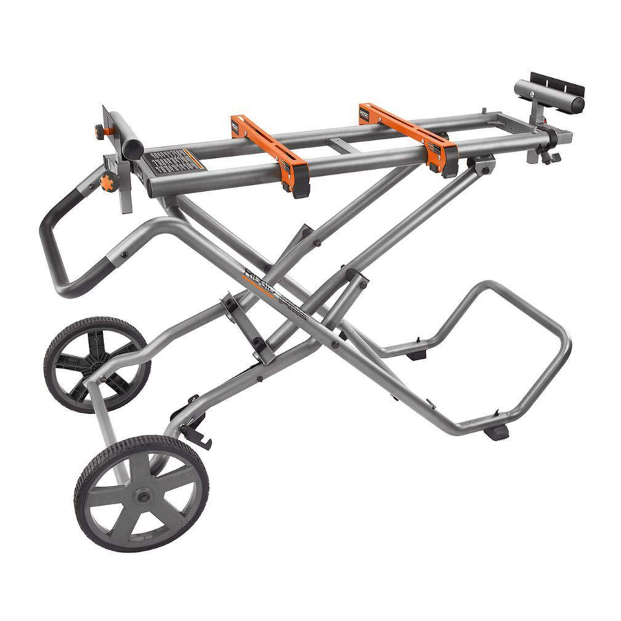
- Page 32 Fig. 1 E - Frame support (support de cadre, apoyo del bastidor) A - Work supports (supports de travail, soportes de la pieza de trabajo) F - MSUV top rails (rails supérieurs du MSUV, rieles superiores B - Locking lever (levier de verrouillage, palanca de fijación) del MSUV) G - Central brace (renfort central, riostra central) C - Quick release saw mounting brackets (supports de montage...
- Page 33 Fig. 2 LOOSE PARTS PIÈCES DÉTACHÉES PIEZAS SUELTAS A - Work stop (butée, tope de trabajo) M - Handle bolt [M8 x 45mm] (boulon de la poignée [M8 x 45mm], B - Work support (support de travail, soporte de la pieza de trabajo) perno del mango [M8 x 45mm]) C - Work stop adjustment knob (bouton de réglage de butée, perilla N - Axle bolt (boulon de essieu, perno de eje)
- Page 34 Fig. 6 Fig. 8 A - Frame support (support de cadre, apoyo del bastidor) B - Wing Nut [M8] (écrou papillon [M8], tuerca de mariposa [M8]) C - Feet (pieds, pies) D - Foot bolt [M8 x 55mm] (boulon de la pied [M8 x 55mm], perno de A - Push the release lever (appuyer le levier de dégagement, aprie- la pie [M8 x 55mm]) te la palanca de afloje)
- Page 35 Fig. 10 Fig. 12 A - Hex nut [M8] (écrou hexagonal [M8], tuerca hexagonal [M8]) B - Lock washer [M8] (rondelle frein [M8], arandela de fijación [M8]) C - Flat washer [M8] (rondelle plate [M8], arandela plana [M8]) D - Bolt [M8 x 30mm or M8 x 50mm] (boulon [M8 x 30mm ou A - Unlocked position (position...
- Page 36 Fig. 14 Fig. 16 A - Thread adjustment knob onto bolt (tournez le bouton de réglage sur le boulon, gire la perilla de ajuste de tornillo) B - Work stop adjustment knob (bouton de réglage de butée, perilla de ajuste de tope de pieza de trabajo C - Work stop (butée, tope de trabajo) D - Work support (support de travail, soporte de la pieza de trabajo)
- Page 37 Fig. 18 HORIZONTAL CLOSED POSITION POSITION HORIZONTALE FERMÉE POSICIÓN DE CIERRE HORIZONTAL Fig. 19 Fig. 20 A - Support arm (bras de support, brazo de soporte) B - Locking lever (levier de verrouillage, palanca de fijación) C - To lock (pour verrouiller, para asegurar ) D - To unlock (pour déverrouiller, para desbloquear) A - Work support (support de travail, soporte de la pieza de trabajo)
- Page 38 Fig. 21 Fig. 22 REAR VIEW VISUALISER ARRIÈRE VISTA TRASEROS A - Pull the lever out to rotate (tirer le levier vers l’extérieur pour tourner, tire de la palanca hacia afuera para girar) B - Rotate to the desired position (turner jusqu’à la position désirée, rote hasta la posición deseada) C - Release the lever to lock (relâcher le...
- Page 39 NOTES / NOTAS...
-
Page 40: Service
ONE WORLD TECHNOLOGIES, INC. P.O. Box 1427 Anderson, SC 29622 USA 1-866-539-1710 powertools.ridgid.com RIDGID is a registered trademark of RIDGID, Inc., used under license. 991000678 12-3-20 (REV:02)
Need help?
Do you have a question about the AC9946 and is the answer not in the manual?
Questions and answers