Table of Contents
Advertisement
Quick Links
Based on P-Series PLC on a Chip
Supports J1939 &
NMEA 2000 Networking
and is VersaCloud M2M
Enabled
HEC-P6XXX Harsh
Environment Controller
Covered Models:
USER'S MANUAL
Technology
TM
HEC-P6000
HEC-P6110
HEC-P6010
HEC-P6200
HEC-P6100
HEC-P6210
Divelbiss Corporation
9778 Mt. Gilead Road,
Fredericktown, Ohio 43019
Revision: 1
Toll Free: 1-800-245-2327
Web: http://www.divelbiss.com
Email: sales@divelbiss.com
2016002.1
Advertisement
Table of Contents

Summary of Contents for Divebiss HEC-P6 Series
- Page 1 USER’S MANUAL Revision: 1 Based on P-Series PLC on a Chip Technology Supports J1939 & NMEA 2000 Networking and is VersaCloud M2M Enabled HEC-P6XXX Harsh Environment Controller HEC-P6000 HEC-P6110 Covered Models: HEC-P6010 HEC-P6200 HEC-P6100 HEC-P6210 Divelbiss Corporation Toll Free: 1-800-245-2327 9778 Mt.
-
Page 2: Table Of Contents
Table of Contents Manual Contents Getting Started How to Use this Manual ............... 4 The HEC-P6XXX Controller Overview ............ 5 The HEC-P6XXX Models & Features Overview ........5 Configuring the HEC-P6XXX Target in EZ LADDER Toolkit ..... 6 Loading the HEC-P6XXX Kernel ............. 7 Getting to Know the HEC-P6XXX ............ - Page 3 Table of Contents CAN Networking Ports ................ 37 FRAM / Retentive Memory ..............40 EEPROM Memory (ON-CHIP) .............. 41 SD Card Memory ................43 Ethernet Communications ..............44 WI-FI Option ..................46 Modbus TCP ..................49 Structured Text Support ..............50 SAE J1939 / NMEA 2000 ..............
-
Page 4: Getting Started
Getting Started This section explains how to read this manual and understand the symbols and information that it contains. To begin using your HEC-P6XXX Controller, you will need to follow these steps: • Install EZ LADDER Toolkit if not already installed (not included). •... -
Page 5: How To Use This Manual
Getting Started How to Use this Manual In this manual, the following conventions are used to distinguish elements of text: BOLD Denotes labeling, commands, and literal portions of syntax that must appear exactly as shown. italic Used for variables and placeholders that represent the type of text to be entered by the user. Used to show key sequences or actual buttons, such as OK, where the user clicks the OK button. -
Page 6: The Hec-P6Xxx Controller Overview
Getting Started The HEC-P6XXX Controller Overview The HEC-P6XXX Harsh Environment Controller is a powerful Harsh Environment Controller with many features and options. The HEC-P6XXX is based on the P-Series PLC on a Chip The HEC-P6XXX boasts the following capabilities based on the model: •... -
Page 7: Configuring The Hec-P6Xxx Target In Ez Ladder Toolkit
Getting Started Configuring the HEC-P6XXX Target in EZ LADDER Toolkit Before you can program and use the HEC-P6XXX Controller, it must be configured as a target within the EZ LADDER Toolkit. For help with installing or using EZ LADDER, please refer to the P-Series EZ LADDER User’s Manual. PROJECT then SETTINGS. -
Page 8: Loading The Hec-P6Xxx Kernel
Getting Started Figure 1.2 - HEC-P6000 Properties Window Loading the HEC-P6XXX Kernel THE HEC-P6XXX WILL NOT FUNCTION UNLESS THIS STEP (KERNEL LOADING) IS COMPLETED. The kernel is the firmware for the controller and to provide greater flexibility and reliability, HEC Controller shipments are factory shipped without a kernel. - Page 9 Getting Started 4. Click the (Compile) button 5. Click the (Monitor) button to change from the ‘Edit’ to ‘Monitor’ Mode. 6. Click the (Connect) button to connect to the target. A dialog will appear automatically when no kernel is PROJECT then BOOTLOADER.
-
Page 10: Getting To Know The Hec-P6Xxx
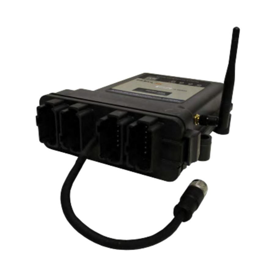
Getting Started Figure 1.4 - Updating the Kernel / Target Getting to Know the HEC-P6XXX The HEC-P6XXX Controller is designed to provide powerful programmable features in a tough, harsh environment resistant package. The main features of the HEC-P6XXX are accessed via four (4) sealed Deutsch connectors that will be referred to as the ‘A’ connec- tor which is grey, the ‘B’... - Page 11 Getting Started Figure 1.5 - HEC-P6XXX Connectors - Front View Antenna Connector Locations Based on HEC-P6XXX model, there can be 0, 1 or 2 antenna connectors. The antenna connectors are for Wi- Fi and Cellular connectivity. The antennas are designed with op- posite genders.
-
Page 12: Assembling / Dis-Assembling The Hec-P6Xxx
Getting Started CONNECTOR ‘C’ (GREEN) CONNECTOR ‘D’ (BROWN) Pin 1 Digital Input 2 / Counter Input 2 Pin 1 DIN Group B: Digital Input 12 Pin 2 Digital Input 3 / Quad Input A Pin 2 DIN Group B: Digital Input 13 Pin 3 Digital Input 4 / Quad Input B Pin 3... -
Page 13: Hec-P6Xxx Configuration Jumpers, Switches And Potentiometers
Getting Started HEC-P6XXX Configuration Jumpers, Switches and Potentiometers To gain the most value of the many features included in the HEC-P6XXX controller, there are many options that may be configured in the field for actual needs. These options are configured using the internal configuration dip switches and jumpers. To configure these switches and jumpers, the HEC-P6XXX must be dis-assembled. - Page 14 Getting Started Switch # Function SW1-1 CNTR Channel 0 Type SW1-2 CNTR Channel 1 Type SW1-3 CNTR Channel 2 Type SW1-4 Quadrature Channel A Type SW1-5 Quadrature Channel B Type SW2-1 Quadrature Channel Index Type SW2-2 Analog Input Channel 0 V/I Select Analog Input = Voltage Analog Input = Current SW2-3...
- Page 15 HEC-P6XXX Features This section explains the Harsh Environment Controller (HEC-P6XXX) hardware features, options and information regarding EZ LADDER Toolkit for basic operation.
-
Page 16: Programming Port
HEC-P6XXX Features Programming Port The HEC-P6XXX is programmed using its Programming Port (COM 0). This RS232 serial port is only to be used for programming using Divelbiss EZ LADDER Toolkit software. This is not a general purpose port and may not be used in any other capacity than programming the controller itself. -
Page 17: Status (Sts) Led
HEC-P6XXX Features Status (STS) LED The operating status of the HEC-P6XXX can be determined the by Status LED. When the Status LED is flashing at a slow rate, approximately once per second, then there is no ladder program executing. When the Status LED is flashing at a fast rate (several times per second), a program has been loaded and it is executing. -
Page 18: Input Power Monitor
HEC-P6XXX Features Figure 2.3 - Input Power Connections - Main Logic Input Power Monitor The power connected to the main logic power input of pins 1 and 2 on connector ‘A’ may be monitored in the ladder diagram program. This input power is optionally connected to analog input 7 (AN7). The configuration switches SW3-3 must be set to ON and SW3-4 must be set to OFF for the power monitor to function. -
Page 19: Mounting
HEC-P6XXX Features Mounting The HEC-P6XXX controller is designed to be panel mounted directly into most environments. The HEC-P6XXX mounts using 4 screws up to 1/4” in diameter. Even though the HEC-P6XXX can be submerged up to 3 meters in water, ideally, when mounting the HEC- P6XXX controller, the end with the connectors should be mounted downward as to promote moisture flow away from the connec- tions. -
Page 20: Counter Inputs
HEC-P6XXX Features DIN11 - DIN13 (variables DIN11 - DIN13) These five (3) inputs are dedicated as digital inputs only. This group has it’s own common pin, allowing this entire group to be configured as sinking or sourcing based on the wiring. As digital input groups DIN6 - DIN10 and DIN11 - DIN13 are separate groups with individual common pins, these two groups can operate at different voltages between 8VDC and 32VDC. - Page 21 HEC-P6XXX Features Figure 2.6 - Typical Digital Input Connections HEC-P6XXX User’s Manual Document #: 2016002.1.pdf PAGE 20 of 60 Divelbiss Corporation • 9778 Mt. Gilead Road • Fredericktown, Ohio 43019 • 1-800-245-2327 • www.divelbiss.com...
- Page 22 HEC-P6XXX Features Figure 2.8 - Selecting Counter / Timer Channel Figure 2.7 - Installing Timer/Counter Device The Timer / Counter Properties window will now appear. From this window, the actual counter/timer channel hardware will be installed. Click the button. The Select Timer/Counter Channel window will appear. From the list provided, select the counter / timer channel to use.
- Page 23 HEC-P6XXX Features Figure 2.9 - Timer/Counter as Free Running Timer Figure 2.10 - Timer/Counter as Counter Timer When configured as a timer, frequency or period may be measured of the signal to the input. This signal is referenced to a 24MHz clock internally.
- Page 24 HEC-P6XXX Features Please note: Individually, the DIN0 - DIN2 inputs are designed to be used as a digital input only or high speed counter/ timer input only. EZ LADDER will allow the placement of contacts and /or TIMERCOUNTER function in any program. Therefore, you can place and use the contacts and the TIMERCOUNTER function block in the same program with the same digital input selected.
-
Page 25: Quadrature Input
HEC-P6XXX Features Quadrature Input As was noted in the Digital Inputs Section, three of the digital inputs (DIN3, DIN4, DIN5) may be utilized together as a quadrature input that can accept signals from a quadrature encoder. When configured as quadrature inputs (DIN3, DIN4 and DIN5 as CHA, CHB and INDEX respectively), can accept frequencies up to 100KHz. -
Page 26: Digital Outputs
HEC-P6XXX Features Figure 2.13 - Installing Quadrature Encoder Interface Figure 2.14 - Quadrature Encoder Properties The switches SW1-4, SW1-5 and SW2-1 configures the type of input for DIN3 to DIN5 respectively. When the switch is in the OFF position, the type is PNP. When the switch is in the ON position, the type is NPN. Refer to the HEC-P6XXX Configuration Jumpers, Switches and Potentiometers section of this manual for switch locations. - Page 27 HEC-P6XXX Features Figure 2.15 - Typical Digital Output Connections HEC-P6XXX User’s Manual Document #: 2016002.1.pdf PAGE 26 of 60 Divelbiss Corporation • 9778 Mt. Gilead Road • Fredericktown, Ohio 43019 • 1-800-245-2327 • www.divelbiss.com...
-
Page 28: Pulse Width Modulation Outputs
HEC-P6XXX Features Each output can drive a load up to maximum current rating listed in the specifications section (resistive) and includes an automatic over-current shutdown safety. In the event an over current condition exists, the output will shut down. This shut down condition is reset when the output is turned off (set to false) in the ladder diagram. -
Page 29: Pwm Channel Load Current Feedback
HEC-P6XXX Features In the PWM Properties Window, using the REMOVE buttons, add the channels of the Outputs that you desire to operate as PWM. Each PWM channel is the same as each DOT channel (DOT0 is the same as PWM0, etc.). Enter the desired base frequency for the PWM output group (if used). -
Page 30: Analog Inputs
HEC-P6XXX Features Analog Inputs The HEC-P6XXX provides 4 on-board, 12-bit resolution analog inputs. Each analog input will accept an input of 0-5VDC, 0-10VDC or 0-20mADC. The analog input ranges and types are configured using internal dip switches. These dip switches should be configured for the correct inputs prior to actually connecting the analog inputs. -
Page 31: Analog Outputs
HEC-P6XXX Features Analog Outputs The HEC-P6XXX provides 2 on-board, 12-bit resolution analog outputs rated 0-10VDC. A calibration potentiometer is provided for minor field calibration (if required) for each channel. To gain access to these potentiometers, the HEC-P6XXX must be dis-assembled. See the Assembling / Dis-assembling the HEC-P6XXX section of this manual. Refer to the HEC-P6XXX Configuration Jumpers, Switches and Potentiometers section of this manual for poteniometer locations. -
Page 32: Real Time Clock
HEC-P6XXX Features Real Time Clock The HEC-P6XXX supports a Real Time Clock based on model. Refer this manual’s Getting Started section for specific models that support the real time clock. The real time clock (after being set) provides the Month, Day, Day of the Week, Year, Hour, Minute and Second. - Page 33 HEC-P6XXX Features Serial Port Connect Pin Functions HEC-P6000 HEC-P6010 / HEC-P6200 / HEC-P6210 Number UART2: RS232 TXD / UART2: RS232 TXD / RS485 A RS485 A UART2: RS232 RXD / UART2: RS232 RXD / RS485 B RS485 B UART3: RS232 TXD / UART2: RS232 TXD / RS485 A RS485 A UART3: RS232 RXD /...
- Page 34 HEC-P6XXX Features With the wiring and configuration complete, to use one or more serial ports, they must be installed in the EZ LADDER diagram proj- ect and configured. In EZ LADDER, from the File Menu at the top, click PROJECT then SETTINGS.
-
Page 35: Modbus Master / Slave (Serial Ports)
HEC-P6XXX Features Modbus Master / Slave (Serial Ports) Modbus Master or Slave may be utilized with the Serial Ports (UARTs). To use Modbus Master or Slave over Serial Ports, Modbus Master/Slave must be installed and configured in the ladder diagram project. Serial Port(s) (UARTs) must be installed prior to installing or configuring the Modbus Master / Slave using Serial. -
Page 36: Serial Print Option (Serial Ports)
HEC-P6XXX Features Figure 2-27 - Add UART Interface - Slave Figure 2-28 - Add UART Interface - Master Serial Print Option (Serial Ports) The Serial Ports (UARTs) may be utilized to send ASCII data serially to an external device. To use the serial ports for this type of communications, the Serial Printing option must be installed in ladder diagram project before it may be used. -
Page 37: Custom Serial Data With Structured Text (Serial Ports)
HEC-P6XXX Features Click the number of times required to save the settings of the Serial Printing and return to the EDIT workspace. Remember to Save your ladder diagram using the menu FILE SAVE SAVE AS. The Serial Print is now installed and configured to use in the ladder diagram program on the HEC-P6XXX controller. Serial Printing uses the SERIAL_PRINT function block. -
Page 38: Can Networking Ports
HEC-P6XXX Features Figure 2-31- PLCHIP-PXX Devices - GPS 5. Click to as needed to close each of the open windows including the HEC-P6000 Properties window. 6. Save your ladder diagram using the menu FILE SAVE SAVE AS to save the current settings in your program. The GPS option is now installed and ready to used in the ladder diagram program / structured text. - Page 39 HEC-P6XXX Features To use the CAN ports in an EZ LADDER diagram project, the actual CAN port Device must be installed. PROJECT then SETTINGS. This will open the Project Settings Window. The HEC- In EZ LADDER, from the File Menu at the top, click P6000 was previously selected.
- Page 40 HEC-P6XXX Features Figure 2.33- Typical CAN Port Connections HEC-P6XXX User’s Manual Document #: 2016002.1.pdf PAGE 39 of 60 Divelbiss Corporation • 9778 Mt. Gilead Road • Fredericktown, Ohio 43019 • 1-800-245-2327 • www.divelbiss.com...
-
Page 41: Fram / Retentive Memory
HEC-P6XXX Features FRAM / Retentive Memory The HEC-P6XXX controllers support two types of on-board non-volatile memory: EEPROM and FRAM. The EEPROM memory is on- chip (on-board the PLC on a Chip) while the FRAM is an independent device. FRAM is the memory that is used to store all Retentive variables in the ladder program. Retentive variables automatically store their values into the FRAM device when a power loss is detected and then the values are read from FRAM and restored automatically when power is restored. -
Page 42: Eeprom Memory (On-Chip)
HEC-P6XXX Features Figure 2.35 - Configure Retentive Memory FRAM AS EEPROM IN EZ LADDER TOOLKIT The FRAM may also be used in EZ LADDER Toolkit as EEPROM memory using the EEPROM_WRITE and EEPROM_READ function blocks. Any memory not allocated as retentive bytes is available to be used as general EEPROM storage. When using the EEPROM_READ or EEPROM_WRITE function blocks, the storage device is selected. - Page 43 HEC-P6XXX Features 5. Click OK. The PLCHIP_Pxx_eeprom Properties dialog will open. Leave the default settings (Num Retentive Bytes set to 0). See Figure 2-38. Click OK. Figure 2-36 - HEC-P6XXX Properties Figure 2-37 - PLCHIP-PXX Devices - EEPROM Figure 2-38 - PLCHIP Pxx_eeprom Properties The HEC-P6XXX’s On-Chip EEPROM should not be used for Retentive Memory.
-
Page 44: Sd Card Memory
HEC-P6XXX Features Special care must be taken when mapping and using the EEPROM on-board memory. Refer to the P-Series EZ LADDER Toolkit manual (EEPROM MEMORY section) for details on using the function blocks and how the memory is mapped including recommendations for controller where values are stored. SD Card Memory The HEC-P6XXX can accept a Micro SD Flash card. -
Page 45: Ethernet Communications
D-CODED M12 connector (4 pins). The Pin-out for the D-CODED Ethernet cable can be found in Figure 2.42. The Ethernet port will operate if the cable is wired as a patch cable or a cross-over cable. Divebiss offers a D-CODE M12 to RJ45 male cable, part number 138-109043 (sold separately). - Page 46 HEC-P6XXX Features The Ethernet Port for the HEC-P6XXX must be enabled prior to it being used in any capacity. It is enabled in the Bootloader screen. The Bootloader screen will only operate if EZ LADDER is connected to an actual HEC-P6XXX controller. To Access the Bootloader: 1.
-
Page 47: Wi-Fi Option
HEC-P6XXX Features Enable Ethernet in Bootloader Enable EZ Ladder Ethernet Communications 12. It is generally recommended to keep the check boxes be checked. The Wi-Fi checkbox should be left un-checked unless the model supports Wi-Fi. The Enable Ethernet in Boot- loader when unchecked prevents the bootloader screen that you are in from being accessed via Ethernet. - Page 48 HEC-P6XXX Features INSTALLING WI-FI IN EZ LADDER TOOLKIT For Wi-Fi supporting models of HEC-P6XXX, EZ LADDER Toolkit (PLC on a Chip) utilize the Wi-Fi connection as an Ethernet connec- tion. To use Wi-Fi, the Ethernet option must be configured in the Bootloader and EZ LADDER Toolkit (Project Settings). Refer to the Ethernet Port Section of this manual.
- Page 49 HEC-P6XXX Features Figure 2-47 - WiFi Setup and Status Up to 10 SSID / Passwords may be saved on the on-board Wi-Fi module. The module searches through the list for in-range SSIDs (APs) and attempts to connect with them based on priority. When removing (deleting) SSIDs, the list should be edited as all remaining SSIDs are listed beginning with the top and leaving no empty spaces in the list.
-
Page 50: Modbus Tcp
HEC-P6XXX Features 13. Click close to close the WiFi Setup and Status window. The Wi-Fi connectivity is now configured and connected to Wi-Fi network and can be used as the programming port. For Modbus TCP or VersaCloud M2M communications, additional configuration is required. Wi-Fi connectivity depends upon the target being in range, with sufficient signal strength and being configured properly for communications over the Wi-Fi network. -
Page 51: Structured Text Support
HEC-P6XXX Features Figure 2-50 - Add Interface Modbus TCP (over Ethernet / Wi-Fi) is now ready to be used on the HEC-P6XXX. Several additional function blocks are used with the Modbus TCP Ethernet port in the ladder diagram project. More on Modbus and the required function blocks is detailed in the P-Series EZ LADDER Toolkit Manual. - Page 52 HEC-P6XXX Features ADD DEVICE J1939 3. Click the button. The PLCHIP-PXX Devices window will open. Locate the in the Devices pane of this window. 4. Click / select J1939 (highlight). Refer to Figure 2-51. Figure 2-51 - PLCHIP-PXX Devices - J1939 .
-
Page 53: Optican Networking
HEC-P6XXX Features Figure 2-52 - CAN / J1939 Properties OptiCAN Networking HEC-P6XXX controllers support the Divelbiss proprietary OptiCAN (CAN Network) protocol. OptiCAN is a register based CAN network that provides a communications method between OptiCAN enabled controllers and devices (PLC on a Chip based) for transmitting / receiving variables (integer, boolean, real and timer). - Page 54 HEC-P6XXX Features PROPERTIES button to the right side of the window. The HEC-P6000 Properties Window will open. Make sure 2. Click the the proper model is selected in the drop-down menu. 3. Click the ADD DEVICE button. The PLCHIP-PXX Devices window will open. Locate the OptiCAN in the Devices pane of this window.
-
Page 55: Cellular Data Option
HEC-P6XXX Features Figure 2-54 - OptiCAN Properties 7. Click to as needed to close each of the open windows including the HEC-P6000 Properties window. FILE SAVE SAVE AS 8. Save your ladder diagram using the menu to save the current settings in your program. OptiCAN communications is now configured and can be used in the ladder diagram project. - Page 56 HEC-P6XXX Features Use ISOLATED BULKHEAD ANTENNA CONNECTION Mounted in Metal Enclosure - Free Mounted - Directly External Mounted Antenna Mounted Antenna Figure 2-55 -Antenna Mounting Options With the antenna properly installed and connected, the Cellular Data option must be installed / enabled in EZ LADDER Toolkit using the Project Settings Menu.
-
Page 57: Versacloud M2M Connectivity
HEC-P6XXX Features Figure 2-56 - PLCHIP-PXX Devices - Cellular VersaCloud M2M Connectivity VersaCloud M2M is a complete, end to end solution for remote monitoring, configuration and control. Using the HEC-P6XXX (or other VersaCloud enabled devices), equipment may be monitored for current status and alarms as well as controlled including configuration changes and remote control of the process. - Page 58 HEC-P6XXX Features Figure 2-57 - PLCHIP-PXX Devices - VersaCloud Note: To select Wi-Fi, choose Ethernet as for Wi-Fi functionality, the P-Series PLC on a Chip sees the Wi-Fi as Ethernet. For all Wi-Fi functionality after Wi-Fi is enabled in the Bootloader - Choose Ethernet.
-
Page 59: Battery Backed Up S-Ram Memory
HEC-P6XXX Features VersaCloud M2M Connectivity is utilized in the ladder diagram program by the VCLOUD Function block. This block is added to the ladder diagram as needed and includes a Properties window when it is placed that determines the Send and Receive variables (data). -
Page 60: Specifications
HEC-P6XXX Features S-RAM SPI Interface Information Function Description Bus / I/O Address SPI Port SPI Port used for S-RAM SPI1 RAM 1 CS S-RAM, Chip Select GPIO10 RAM 1 CS S-RAM, Chip Select GPIO11 RAM 1 CS S-RAM, Chip Select GPIO29 RAM 1 CS S-RAM, Chip Select... - Page 61 HEC-P6XXX Features 14 Digital Outputs Total Divided into 3 groups of 4, 1 group of 2. Sourcing, 8-32VDC Operation. Over-current Protected All outputs rated up to 2 Amps Maximum (8 Amps Max. per group). SEE NOTE 1 Pulse Width Modulation (12 Outputs), 1Hz to 1KHZ operating range Digital Outputs Each group has independent power source pin.
Need help?
Do you have a question about the HEC-P6 Series and is the answer not in the manual?
Questions and answers