Advertisement
Quick Links
VOC-ROOM
Installation & Operation Instructions
GENERAL INFORMATION
VOCs are emitted as gases from certain solids or
liquids, such as building materials and furnishings,
o ce equipment, cleaners and disinfectants, etc.
These types of contaminants directly a ect indoor air
quality and occupant comfort. Measuring and
communicating VOC levels back to the BAS will help
users adjust ventilation to maintain proper IAQ
levels. These units utilize a high-performance metal
oxide sensor and will output TVOC levels in a range
from 0-1000 ppb. All units come equipped with both
analog and RS485 Modbus RTU outputs easily
interface into existing BAS systems.
IMPORTANT PRECAUTIONS
Read the following instructions carefully before
using the indoor air quality sensor described in
this document to avoid erroneous readings and
to prevent the device from permanent damage.
• The sensor must not be exposed to high
concentrations
ammonia, silicone vapour or cigarette-smoke
in order to avoid poisoning the sensitive
layer.
MOUNTING INSTRUCTIONS
For optimal temperature readings, follow these
tips:
• Do not install on external walls.
• Avoid air registers, di users, vents, and windows
• Avoid con ned areas such as shelves, closed cabinets,
closets, and behind curtains.
• Eliminate and seal all wall and conduit penetrations.
Air migration from wall cavities may alter
temperature readings.
• Do not install near heat sources. eg: lamps, radiators,
direct sunlight, copiers, chimney walls, walls
concealing hot-water pipes
Automation Components, Inc.
2305 Pleasant View Road | Middleton, WI 53562
Phone: 1-888-967-5224 | Website: workaci.com
of
organic
solvents,
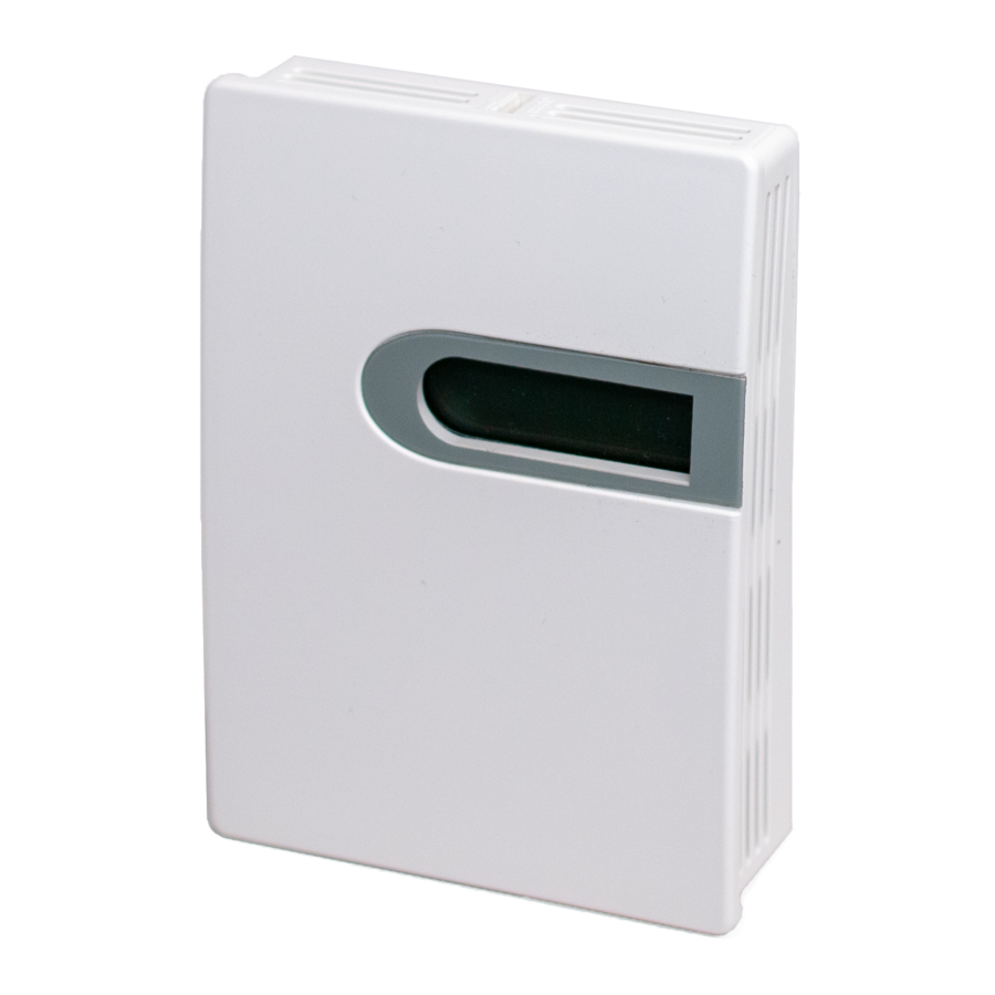
FIGURE 1: ENCLOSURE
DIMENSIONS
3.268"
(82.00 mm)
FIGURE 2: OPENING COVER
Separate the cover from the base by inserting a
at head screwdriver into the top slot marked
"OPEN". Pry the cover forward.
Attach the base directly to the wall or to a
standard 2" x 4" junction box using (2) #6-32 x 1"
screws.
Page 1
Phone: 1-888-967-5224
Website: workaci.com
.984"
(25.00 mm)
1.205"
(30.60 mm)
Version: 2.0
I0000939
Advertisement

Related Manuals for aci VOC-ROOM


Summary of Contents for aci VOC-ROOM
- Page 1 VOC-ROOM Phone: 1-888-967-5224 Installation & Operation Instructions Website: workaci.com FIGURE 1: ENCLOSURE GENERAL INFORMATION DIMENSIONS VOCs are emitted as gases from certain solids or liquids, such as building materials and furnishings, .984" 3.268" (25.00 mm) (82.00 mm) o ce equipment, cleaners and disinfectants, etc.
- Page 2 VOLTAGE SPIKES WHEN DE-ENERGIZING THAT CAN CAUSE MALFUNCTION OR DESTRUCTION OF ELECTRONIC CIRCUITS. ACI recommends 16 to 26 AWG twisted pair wires or shielded cable for all transmitters. ACI recommends using BELDEN 3105 for communi- cation(Modbus) wiring. This wire has 120 ohm input impendence.
- Page 3 RELAY SET POINT SELECTION The relay set point can be changed by the jumper selections shown below(Fig 6). The default mode is Balance (230 ppb). FIGURE 6: RELAY SET POINT SELECTION Good Air Quality Balance (Default) Energy Saving MODE RELAY SET POINT Energy Saving (1) 300 ppb Balance (Default)(2)
-
Page 4: Address Selection
The device that requests information is called the Modbus Master and the devices giving the information are Modbus Slaves. The Modbus sensors are slave devices and the number of Data Bits needs to be the same as in the Master device con guration. ACI’s Modbus RTU sensors utilize 8 data bits during communication exchange. - Page 5 MODBUS RTU MAP Register Address Type De nition Remarks 40001, 00000 Signed Product code Product code 40002, 00001 Signed Equivalent CO2 value equivalent CO2 value, Unit: ppm 40003, 00002 Signed VOC measured value VOC measured value, Unit: ppb 40004, 00003 Signed Reserved 40005, 00004...
-
Page 6: Product Specifications
ABS Plastic / UL94V-0 WARRANTY The ACI VOC Room Series are covered by ACI’s Two (2) Year Limited Warranty, which is located in the front of ACI’S SENSORS & TRANSMITTERS CATALOG or can be found on ACI’s web site: www.workaci.com. - Page 7 Page 7 Automation Components, Inc. Version: 2.0 2305 Pleasant View Road | Middleton, WI 53562 I0000939 Phone: 1-888-967-5224 | Website: workaci.com...
- Page 8 Automation Components, Inc. 2305 Pleasant View Road Middleton, WI 53562 Phone: 1-888-967-5224 Website: workaci.com Page 8 Automation Components, Inc. Version: 2.0 2305 Pleasant View Road | Middleton, WI 53562 I0000939 Phone: 1-888-967-5224 | Website: workaci.com...