
Subscribe to Our Youtube Channel
Summary of Contents for Itec ITECNET SPIDERLINE 16
- Page 1 SPIDERLINE 16 MANUAL VERSION 1.0, MAY 2013 Designed and Manufactured by ITEC Tontechnik und Industrieelektronik GesmbH 8200 Laßnitzthal 300 Austria / Europe...
-
Page 2: Dear Customer
For knowing the entire system, all its possibilities and for executing the necessary confi guration tasks the software manual is required in addition. Please observe during the installation / operation of the ITEC SpiderLine16 all listed safety instructions in this manual; furthermore data and examples provided ensuring the optimum usage of the device. -
Page 3: Safety Instructions
When installing the device, the local connecting conditions, the required protective measures and all relevant standards have to be observed. The installation and confi guration of the ITEC SpiderLine16 must be performed by trained personnel only. For the confi guration the original software ITEC NetDesign has to be used exclusively. - Page 4 SPIDERLINE 16 ITEC SPIDERLINE 16 www.itec-audio.com...
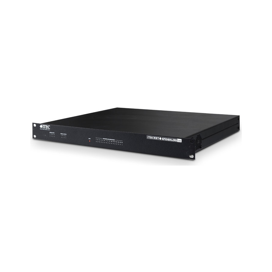
- Page 5 At the same time, a huge number of system data, measure- ment data and IOs are controlled and transmitted. With four audio inputs, four audio outputs, serial ports and I/Os the SpiderLine16 is one of the most important system components. ITEC SPIDERLINE 16 www.itec-audio.com...
-
Page 6: Connectors On The Rear Panel
10 VDC power supply for external control devices (e.g remote ranel) Logic Outputs (see chapter logic outputs) Logic Inputs (see chapter logic inputs) Fault relay (See chapter fault relay) ground connections (See chapter mass concept) max. cable section 4 mm ITEC SPIDERLINE 16 www.itec-audio.com... - Page 7 Speaker lines: switched 100 Volt outputs connecting to the individual lines 100V line inputs of the amplifi ers 100V line inputs of the back-up power amplifi ers Maximum cable section for all terminals 1.5 mm - unless otherwise stated. ITEC SPIDERLINE 16 www.itec-audio.com...
- Page 8 +12V Gain MIC/LINE OUTPUT UNIT 2 Delay OUT 2 IN 2 +12V Gain MIC/LINE OUTPUT UNIT 3 Delay OUT 3 IN 3 +12V Gain OUTPUT UNIT 4 Delay OUT 4 MIC/LINE IN 4 Line Detection DSP ITEC SPIDERLINE 16 www.itec-audio.com...
- Page 9 Short Circuit, End of Line Earth fault Detection Control Earth fault Measurement 1 –16 A / D Pilot Amp Signal D / A Control Generator DSP2 A / D Line Detection, IOs Control A / D ITEC SPIDERLINE 16 www.itec-audio.com...
-
Page 10: Signal Routing
OUT4 External Amplifi ers AMP 1 AMP 2 AMP 3 AMP 4 BACK-UP 1 BACK-UP 2 BACK-UP 3 BACK-UP 4 B.Up1 B.Up2 B.Up3 B.Up4 LS-BUS Earth fault Earth fault PILOT- Short Circuit/EOL Short Circuit/EOL SEAKER LINES ITEC SPIDERLINE 16 www.itec-audio.com... -
Page 11: Power Supply 24 V Dc
Thus, all conventional microphones and media players can properly be adjusted. Phantom power is switchable per channel (12V). Signal Signal Audio outputs The 4 outputs are balanced as well with XLR connectors on the rear cover. The maximum output level is +15 dB Signal Signal ITEC SPIDERLINE 16 www.itec-audio.com... -
Page 12: Digital Inputs
The device has 8 digital open collector transistor outputs. They are used for switching relays, lamps of lo- wer power, etc. Typical applications are the display of faults, switching off other audio devices during an announcement and more. ITEC SPIDERLINE 16 www.itec-audio.com... -
Page 13: The Serial Interface
Operated in parallel with the RS 232 interface, to be used for up-mentioned functionalities, for distances of up to 500 meters of cable. With the RS 485 interface up to 16 devices can be connected in parallel (e.g. ITEC UP remote control panel). -
Page 14: Ethernet Interface
Fault Operating A potential-free relay contact used to display the operating status is available. In case the device is not operating or during a fault condition, the relay is released, during normal operation it is activated. ITEC SPIDERLINE 16 www.itec-audio.com... - Page 15 24VDC supply and housing (Chas- sis Ground). Usually „Signal Ground“ gets the connection to the ground (earth) through the signal terminals of the power amplifi ers or by connection to other systems and must/should not be connected separately. ITEC SPIDERLINE 16 www.itec-audio.com...
- Page 16 48 V AC/DC / 500 mA NETWORK Ethernet 100 Base-TX, IEEE 802.3u No responsibility is taken for the correctness of this information - Specifi cations subject to change ITEC- Tontechnik und Industrieelektronik GesmbH, A-8200 Lassnitzthal 300 Tel.: +43 (0)3133 / 3780-0, offi ce@itec-audio.com, www.itec-audio.com...
Need help?
Do you have a question about the ITECNET SPIDERLINE 16 and is the answer not in the manual?
Questions and answers