Table of Contents
Advertisement
Quick Links
VoIP Electronic Paging Modules
Confidentiality Notice .....................................................................................................................1
Computer Software Copyrights ......................................................................................................1
General Information .......................................................................................................................1
Features and Functions .......................................................................................................................... 2
Available Models ..................................................................................................................................... 2
System Requirements and Limitations ................................................................................................. 2
Multicast Broadcasts .............................................................................................................................. 3
Safety and General Information ............................................................................................................ 3
Outdoor Product .................................................................................................................................... 3
Antenna Care ........................................................................................................................................ 3
Electromagnetic Interference/Compatibility ......................................................................................... 3
Operational Cautions ............................................................................................................................ 4
Safe Handling of CMOS Integrated Circuit Devices ........................................................................... 4
Installation ......................................................................................................................................5
Important Safety Information ............................................................................................................... 5
Outdoor Product .................................................................................................................................... 6
Antenna Care ........................................................................................................................................ 6
Cable Installation Safety Considerations .............................................................................................. 6
Mechanical Receipt Inspection .............................................................................................................. 6
Mount the Paging Module ...................................................................................................................... 6
Open the Module ..................................................................................................................................... 8
Field Wiring ........................................................................................................................................... 10
Power Connection ............................................................................................................................... 10
Speaker Connection ............................................................................................................................ 11
Output Contact Connections ............................................................................................................... 11
Opto Output Connection ..................................................................................................................... 11
Antenna Connection ............................................................................................................................ 11
Programming ................................................................................................................................12
First Time WiFi Interface Setup (Model 10458-801 only) ............................................................... 12
Reset WiFi Interface Configuration (Model 10458-801 only) ........................................................... 15
VoIP Paging Module Setup .................................................................................................................. 15
VoIP Paging Module Initial Network Configuration ........................................................................ 15
GAI-TRONICS 3030 KUTZTOWN RD. READING, PA 19605 USA
610-777-1374 ◼ 800-492-1212 ◼ Fax: 610-796-5954
V
ISIT WWW
G A I - T R O N I C S
A H U B B E L L C O M P A N Y
Wired and WiFi
T
A B L E O F
.
-
.
GAI
TRONICS
COM FOR PRODUCT LITERATURE AND MANUALS
®
C
O N T E N T S
Pub. 42004-464D
Advertisement
Table of Contents

Summary of Contents for Hubbell GAI-Tronics 10458-701
-
Page 1: Table Of Contents
Pub. 42004-464D G A I - T R O N I C S ® A H U B B E L L C O M P A N Y VoIP Electronic Paging Modules Wired and WiFi A B L E O F O N T E N T S Confidentiality Notice ........................1 Computer Software Copyrights ......................1... - Page 2 Table of Contents Pub. 42004-464D Close the VoIP Electronic Paging Module ..................15 Maintenance ..........................16 VoIP Circuit PCBA Pushbuttons ......................16 Reset ..............................16 Factory ..............................16 Status Indication ........................... 17 Power ..............................17 Heartbeat ............................. 17 Link ..............................17 Speed ..............................
-
Page 3: Confidentiality Notice
Pub. 42004-464D G A I - T R O N I C S ® A H U B B E L L C O M P A N Y VoIP Electronic Paging Modules Wired and WiFi Confidentiality Notice This manual is provided solely as an installation, operation, and maintenance guide and contains sensitive business and technical information that is confidential and proprietary to GAI-Tronics. -
Page 4: Features And Functions
Pub. 42004-464D VoIP Electronic Paging Modules—Wired and WiFi Page 2 of 20 Features and Functions The GAI-Tronics Models 10458-701 VoIP and 10458-801 VoIP WiFi electronic paging modules are equipped with the following features: • wired or WiFi • one-way broadcasting from an IP network •... -
Page 5: Multicast Broadcasts
Pub. 42004-464D VoIP Electronic Paging Modules—Wired and WiFi Page 3 of 20 • SNMP server (for reporting via simple network management protocol) • SNTP server (to synchronize the internal clock) • STUN server (for NAT firewall traversal) Dedicated systems, such as Gatekeepers, VoIP-enabled PABXs or soft PABXs may also provide these functions. -
Page 6: Operational Cautions
Pub. 42004-464D VoIP Electronic Paging Modules—Wired and WiFi Page 4 of 20 Operational Cautions Hospitals or Health Care Facilities To avoid electromagnetic interference and/or compatibility conflicts, turn off the radio in any facility where posted notices instruct you to do so. Hospital or health care facilities may be using equipment that is sensitive to external RF energy. -
Page 7: Installation
Pub. 42004-464D VoIP Electronic Paging Modules—Wired and WiFi Page 5 of 20 • All electrically powered test equipment should be grounded. Apply the ground lead from the test equipment to the circuit module before connecting the test probe. • If a circuit module is removed from the system, it is desirable to lay it on a conductive surface (such as a sheet of aluminum foil) which is connected to ground through 100-kilohms of resistance. -
Page 8: Outdoor Product
Pub. 42004-464D VoIP Electronic Paging Modules—Wired and WiFi Page 6 of 20 Outdoor Product Power Lines—Do not locate this product in the vicinity of overhead power lines, electric lights, power circuits, or where it may contact such power lines or circuits, as this contact might be fatal. Refer to the National Electrical Code Article 800 regarding installation. - Page 9 Pub. 42004-464D VoIP Electronic Paging Modules—Wired and WiFi Page 7 of 20 Figure 2. Mounting Plate P:\Standard IOMs - Current Release\42004 Instr. Manuals\42004-464D.docx 03/20...
-
Page 10: Open The Module
Pub. 42004-464D VoIP Electronic Paging Modules—Wired and WiFi Page 8 of 20 Figure 3. Component Identification Open the Module The VoIP paging module must be opened for programming and installation: Bench programming and testing is recommended. 1. Remove the assembly from the carton and position on a flat surface. 2. - Page 11 Pub. 42004-464D VoIP Electronic Paging Modules—Wired and WiFi Page 9 of 20 Figure 4: Electronic Paging Module Assembly (Model 10458-701 shown) Figure 5: Electronic Paging Module (opened) P:\Standard IOMs - Current Release\42004 Instr. Manuals\42004-464D.docx 03/20...
-
Page 12: Field Wiring
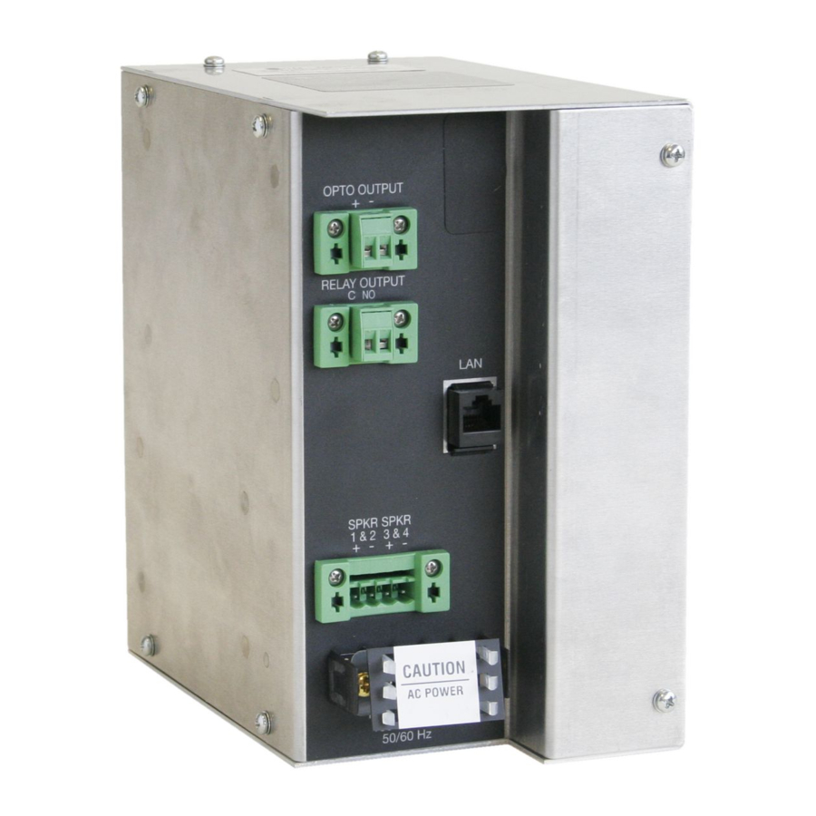
Pub. 42004-464D VoIP Electronic Paging Modules—Wired and WiFi Page 10 of 20 Field Wiring The paging modules have terminal blocks on the front of the assembly for all field wiring. The terminal block labels indicate their functionality (see Figure 6). WARNING —Do not apply power until all the connections are wired. -
Page 13: Speaker Connection
Pub. 42004-464D VoIP Electronic Paging Modules—Wired and WiFi Page 11 of 20 Speaker Connection 1. Install all speaker kits and the antenna kit (for WiFi installations). Make sure all wires and cables from the components are at the bottom of the 234 series communication tower. -
Page 14: Programming
Pub. 42004-464D VoIP Electronic Paging Modules—Wired and WiFi Page 12 of 20 Programming : The 10458-701 and -801 VoIP and VoIP WiFi electronic paging modules include the same embedded website as GAI-Tronics’ VoIP and VoIP WiFi telephones. There are many programmable parameters utilized by the VoIP telephones that are not utilized by the VoIP paging modules. - Page 15 Pub. 42004-464D VoIP Electronic Paging Modules—Wired and WiFi Page 13 of 20 The STA I web page opens: NTERFACE ETTING Figure 8. WiFi Interface STA Interface Setting Web page button, to the right of in the AP’s SSID field, to find the WiFi network that the 7.
- Page 16 Pub. 42004-464D VoIP Electronic Paging Modules—Wired and WiFi Page 14 of 20 The web page will show Set Successfully, Restart to use new setting after the configuration has updated. 11. Click on the selection. EVICE ANAGEMENT The D webpage opens. EVICE ANAGEMENT Figure 10.
-
Page 17: Reset Wifi Interface Configuration (Model 10458-801 Only)
Pub. 42004-464D VoIP Electronic Paging Modules—Wired and WiFi Page 15 of 20 Reset WiFi Interface Configuration (Model 10458-801 only) Use this procedure to erase the current WiFi configuration in the telephone and configure the WiFi adapter with the factory default settings: 1. -
Page 18: Maintenance
Pub. 42004-464D VoIP Electronic Paging Modules—Wired and WiFi Page 16 of 20 Maintenance VoIP Circuit PCBA Pushbuttons Reset Press the RESET button momentarily to warm reboot the telephone (see Figure 11). The telephone maintains the current configuration. Factory Use the FACTORY button (see Figure 11) to erase the current configuration and restore the factory default settings: 1. -
Page 19: Status Indication
Pub. 42004-464D VoIP Electronic Paging Modules—Wired and WiFi Page 17 of 20 Status Indication Power The ON LED, located on the VoIP PCBA (see Figure 11), illuminates when power is applied to the telephone. Heartbeat The HB LED, located on the VoIP PCBA (see Figure 11), flashes when communication over the LAN is established. -
Page 20: Reference Documentation
Pub. 42004-464D VoIP Electronic Paging Modules—Wired and WiFi Page 18 of 20 Reference Documentation VoIP Telephone Basic Configuration Guide ................. 42004-548 VoIP Telephone Programming Guide ................. 502-20-0171-001 Specifications Power Options AC Power Input voltage ......................120/240 V ac, 50/60 Hz Input current .................. -
Page 21: Environmental
Pub. 42004-464D VoIP Electronic Paging Modules—Wired and WiFi Page 19 of 20 Model 10458-701 ......................4.5 lb (2.04 kg) Model 10458-801 ......................5.0 lb (2.27 kg) Environmental Temperature range ................. −4 ºF to +140 ºF (−20 ºC to +60 ºC) Humidity ...................... -
Page 22: Fcc Licensing Information
Pub. 42004-464D VoIP Electronic Paging Modules—Wired and WiFi Page 20 of 20 FCC Licensing Information Your radio operates on General Mobile Radio Service (GMRS), Private Land Mobile Radio Service, Amateur Radio Service, Aeronautical Mobile, or Maritime Mobile Service frequencies and is subject to the Rules and Regulations of the Federal Communications Commission (FCC). - Page 23 Warranty Equipment. GAI-Tronics warrants for a period of one (1) year from the date of shipment, that any GAI-Tronics equipment supplied hereunder shall be free of defects in material and workmanship, shall comply with the then-current product specifications and product literature, and if applicable, shall be fit for the purpose specified in the agreed upon quotation or proposal document.
Need help?
Do you have a question about the GAI-Tronics 10458-701 and is the answer not in the manual?
Questions and answers