Advertisement
www.varilight.co.uk
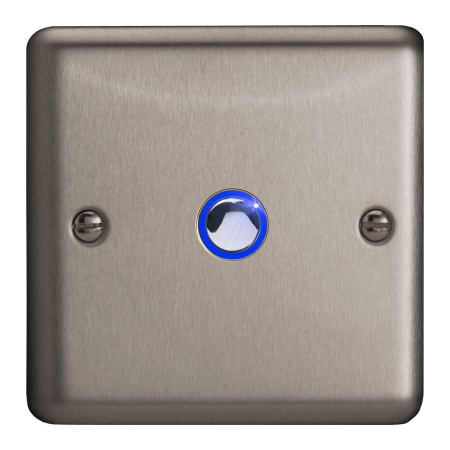
Thank you for choosing a VARILIGHT V-Pro Eclipse intelligent trailing-edge touch/remote control dimmerswitch. This dimmer is suitable for 1-way
circuits. For 2-way (or multi-way switching) use a master unit with any number of V-Pro dimming slaves. N.B. This unit cannot be used in conjunction
with conventional switches in a 2-way circuit. Use only on an electricity supply of 216-253V a.c.
This dimmerswitch features V-Pro intelligent load detection
Which enables it to adapt to many different types of lighting load.
When the dimmer is switched on it will detect the load and adjust
its dimming pattern accordingly. Should you decide to change your
lighting at some time in the future then the dimmer will detect the
change and adapt its dimming pattern accordingly.
This product complies with European Safety Regulations
(IEC 669-2-1 or BSEN 60669-2-1) when used in lighting circuits
containing MCBs (minature circuit breakers). These can be rated
at 6A, 10A or 16A (preferably 6A for lighting circuits). Your
Guarantee is not affected if you have an older lighting circuit
protected by fuse wire links.
THIS SWITCH IS SUITABLE FOR
Mains voltage incandescent GLS or candle-shaped bulbs;
Good quality dimmable electronic low voltage
transformers (including those requiring trailing-edge control)
[see "Transformers" box on the right];
GU10 or similar good quality mains halogen bulbs
Dimmable CFLs
Dimmable LEDs
Always observe the recommended maximum load
[see "Overload Protection" box on the right]
THIS SWITCH IS NOT SUITABLE FOR
Non-dimmable fluorescent bulbs and tubes;
Wire-wound or toroidal transformers;
Electric motors.
FITTING YOUR DIMMERSWITCH:
Read the instructions below carefully. Incorrect installation may damage the dimmer beyond repair. In case of any doubt or difficulty consult a
qualified electrician.
1. Switch off at the mains, then remove the existing switch and disconnect the wiring from the switch terminals at the rear, taking note of the present
wiring of the switch and the marking on the terminals. Where there are two or more wires together in the old switch, they must be kept together in
the dimmerswitch.
2. Ensure that any wall box is free of plaster lumps or projecting screw heads. Dimmerswitches on single-sized plates can be fitted to wall boxes having
60.3mm screw fixing centres and those with double-sized plates to wall boxes with 120.6mm fixing centres. Most models can be fitted into a box with
a minimum depth of 25mm. A box having 4 fixing lugs cannot be used without modifying it. The top and bottom lugs must be broken off or bent flat.
3. To connect the wiring for 1-way or 2-way circuits refer to the diagrams overleaf under the heading "Typical Lighting Circuits". Take care that no bare
wires project out of the terminals. Keep wires together in a terminal if they were together in your old switch.
4. Dimmerswitches having a metal front plate must be earthed by means of the earthing point on the dimmer.
5. After connecting the wires screw the dimmerswitch gently into the wall box so that the front plate is not distorted or cracked. Do not trap the wiring
between the rear of the dimmer and the back of the wall box.
6. Once installation is complete. Switch on the mains supply and switch on the dimmer, turning the control knob to give the desired light level.
1-Way, 2-Way and Multi-Way Circuits
In 1-way lighting circuits the light(s) are controlled by one switch. This dimmer should replace that switch. The live wire must be connected to the
terminal marked "Live↓" and the "load" wire to the terminal marked "
For 2-way or Multi-way circuits (where the light(s) are controlled by more than one switch) use this dimmer and any number of VARILIGHT dimming
slaves (total cable length from the master to the last slave should be no more than 50m) following the wiring diagrams below. It is not possible to use a
conventional switch in combination with this type of dimmer. To fit 2, 3 or 4-gang dimmers treat each group of terminals at the back of the unit as a
separate dimmer, wiring them into the lighting circuits as above. You may need a short length of wire to connect together the "Live↓" terminals.
Fig 1. Wiring for 1-Way Circuits
Instructions For Fitting VARILIGHT
Intelligent Trailing Edge
Touch / Remote Control Dimmers
Fig 2. Wiring for Multi-Way Circuits
OVERLOAD PROTECTION:
As a safety feature, this dimmer is protected against overload and
overheating. (N.B. Some types of bulb can draw more current as
they age and overload the dimmer).
If the dimmer becomes too hot it will attempt to handle the
overload by reducing the brightness of the lamps. If it is unable to
do so the dimmer will automatically turn the lights off until the
overload is removed and the dimmer is switched off and then
switched back on again.
TRANSFORMERS:
Use only with quality dimmable electronic transformers. For
optimum performance choose VARILIGHT transformers*.
To calculate load, add the VA ratings of the transformers (not
the wattage of the bulbs). Choose transformers with a maximum
rating close to their lamp load (eg. Use a 50VA,, 60VA or 70VA
transformer to control a 50W low voltage bulb).
N.B. Certain transformers may not behave according to their
power rating when used with a dimmer. An overload will result
in the safety features of this dimmer turning down the brightness.
If so, change your transformer(s) (VARILIGHT transformer(s)
recommended); or remove one (or some) transformer(s) from the
circuit; or choose a higher rated dimmer instead.
* If a transformer appears as a highly inductive load, e.g. Wire-
wound or toroidal transformers, the dimmer will not work. To
protect itself it will turn off within 1 second.)
".
Fig 3. Alternative Wiring for Multi-Way Circuits
JQI
Reg. 802
Advertisement
Table of Contents

Related Manuals for Varilight V-Pro Eclipse

Summary of Contents for Varilight V-Pro Eclipse
- Page 1 ". For 2-way or Multi-way circuits (where the light(s) are controlled by more than one switch) use this dimmer and any number of VARILIGHT dimming slaves (total cable length from the master to the last slave should be no more than 50m) following the wiring diagrams below. It is not possible to use a conventional switch in combination with this type of dimmer.
- Page 2 4. Why won’t my dimmer respond to the remote control? Check batteries are not flat and are connected properly to the contacts in the casing. Make sure you point the remote control in the direction of the switch and that there is nothing in the way to block the signal. Move closer to the switch. For best results use the VARILIGHT handset.
Need help?
Do you have a question about the V-Pro Eclipse and is the answer not in the manual?
Questions and answers