Table of Contents
Advertisement
Quick Links
Advertisement
Table of Contents

Subscribe to Our Youtube Channel
Summary of Contents for Maxx Vengeance 3
- Page 1 Vengeance 3 SMB Network Appliance User Manual...
-
Page 2: Disclaimers
Disclaimers This manual has been carefully checked and believed to contain accurate information. Maxxwave assumes no responsibility for any infringements of patents or any third party’s rights, and any liability arising from such use. Maxxwave does not warrant or assume any legal liability or responsibility for the accuracy, completeness or usefulness of any information in this document. -
Page 3: Safety Approvals
Most electronic components are sensitive to static electrical charge. Disconnect the power cords from the Vengeance 3 before making any installation. Be sure both the system and the external devices are turned OFF. Sudden surge of power could ruin sensitive components. Make sure the Vengeance 3 is properly grounded. -
Page 4: Table Of Contents
Table of Contents Disclaimers ..................... .i Safety Approvals ................... .ii Safety Precautions ..................ii Chapter 1 Introduction .......... 1 General Description ................1 Features ....................1 Specifications ..................2 Block Diagram ..................5 Dimensions and Outlines ..............5 I/O Outlets .................... 6 Front Panel .................... - Page 5 Installing the Memory ................22 2.5.2 Installing the Hard Disks................22 2.5.3 Appendix A LAN Bypass Configuration ....23 About LAN Bypass..................23 LAN Bypass Register Configuration ............24 Appendix B WDT Timer for System Reset ....26 Appendix C LAN Module Expansion .......
-
Page 6: Chapter 1 Introduction
NA591’s supports data protection of LAN bypass for fail- over option by LAN module. For storing event log data, the Vengeance 3 utilizes two 2.5” SATA HDDs. And Vengeance 3 supports four dual channel up to 128GB DDR4-2666 non-ECC/ECC memory and one standard PCIe x8 expansion slot (PCIe x4 signal) for optional network security card. -
Page 7: Specifications
System Chipset Intel® C246 System Memory Vengeance 3: 4 x DDR4 2666 DIMM sockets, up to 128GB none-buffer none- ECC / ECC memory by CPU SKU BIOS AMI 256Mbit PnP Flash BIOS with function of BIOS redirected to COM port ... - Page 8 Controller Winbond NCT6102D CPU temperature, system temperature, power and fan speed detection Expansion Slot Vengeance 3 supports four LAN modules & one PCIex8 slot through optional Riser card ( via PCH only PCIe x4 signal). Introduction...
- Page 9 Vengeance 3 User’s Manual Power Supplies 400W single power supply 400W redundant power supply (1+1) Note: Indicates to unplug all AC power cord(s) to disconnect AC Power OS Compatibility Linux kernel 4.14 above Mechanical/Environmental ...
-
Page 10: Block Diagram
Vengeance 3 User’s Manual Block Diagram Dimensions and Outlines The following diagram shows you dimensions and outlines of the Vengeance 3 Series. Default: 2 LAN ports max up to 34 LAN ports Introduction... -
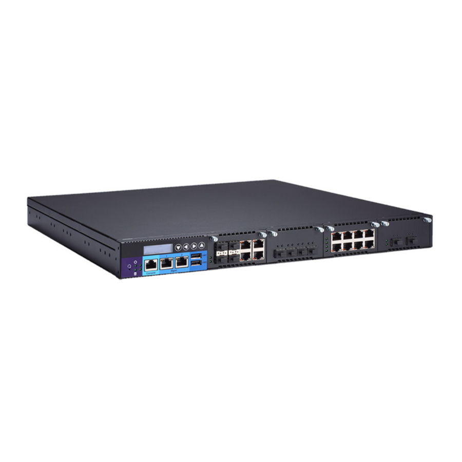
Page 11: I/O Outlets
Vengeance 3 User’s Manual I/O Outlets Locate front and rear panel I/O outlets on the Vengeance 3 Series server to connect serial and Ethernet interface devices. 1.6.1 Front Panel Maximum Throughput Slot 1 and 2: MAX 60Gbps Slot 3 and 4: MAX 30Gbps Back Slot: MAX 60Gpbs ... -
Page 12: Rear Panel
Vengeance 3 User’s Manual Transfer Rate for LAN port The double-color LED light indicates 10/100/1000Mbps transfer rate. LED Light Color Transfer Rate Dark 10Mbps Green 100Mbps Orange 1000Mbps If the LED is dark and Active/Link LED is lighting on flashing, the transfer rate should be 10Mbps. -
Page 13: Hardware And Installation
The Vengeance 3 Series are convenient for your various hardware configurations. This chapter will help you get familiar with the hardware. Check List The package bundled with your Vengeance 3 Series should contain the following items: The Vengeance 3 Series network appliance hardware platform ... -
Page 14: Board Layout
Vengeance 3 User’s Manual Board Layout BOTTOM Hardware and Installation... -
Page 15: Jumper Settings
Vengeance 3 User’s Manual Jumper Settings Jumper is a small component consists of jumper clip and jumper pins. Install jumper clip on 2 jumper pins to close. And remove jumper clip from 2 jumper pins to open. Below illustration shows how to set up jumper. -
Page 16: Auto Power Button Model Jumper (Jp3)
Vengeance 3 User’s Manual 2.3.2 Auto Power Button Model Jumper (JP3) Description Function Jumper Setting Always Power Off ATX Mode Auto Power Button Mode Selection Always Power On (Default) Connectors Signals go to other parts of the system through connectors. Loose or improper connection might cause problems, please make sure all connectors are properly and firmly connected. -
Page 17: Mini Card Connector For Msata (Cn1)
Vengeance 3 User’s Manual 2.4.1 Mini Card Connector for mSATA (CN1) This is a 52-pin connector which is commonly used for SATA device. Signal Signal No use +3.3VSB No use Ground (GND) No use +1.5V No use No use Ground (GND) -
Page 18: 2280 Connector For Pciex4(Cn2)
Vengeance 3 User’s Manual 2.4.2 M.2 2280 Connector for PCIeX4(CN2) This is a 75-pin connector which is commonly used for PCIe device. Pins Signals Pins Signals +3.3V +3.3V PCIE_RXN_3 PCIE_RXP_3 LED1# PCIE_TXN_3 +3.3V PCIE_TXP_3 +3.3V +3.3V PCIE_RXN_2_ +3.3V PCIE_RXP_2 PCIE_TXN_2_... -
Page 19: Atx Power Connector (Cn3)
Vengeance 3 User’s Manual 2.4.3 ATX Power Connector (CN3) Steady and sufficient power can be supplied to all components on the board by connecting the power connector. Please make sure all components and devices are properly installed before connecting the power connector. -
Page 20: Internal Usb 3.1 Gen1 Connector (Cn8)
Vengeance 3 User’s Manual 2.4.5 Internal USB 3.1 Gen1 Connector (CN8) The CN8 is a 19-pin internal connector for installing versatile USB 3.1 compliant peripherals. Signal Signal VBUS0 SSRX0- VBUS1 SSRX0+ SSRX1- SSRX1+ SSTX0- SSTX0+ SSTX1- SSTX1+ USB0- USB0+ USB1- USB1+ ®... -
Page 21: Usb Port Connectors (Usb1~2)
Vengeance 3 User’s Manual 2.4.8 USB Port Connectors (USB1~2) The 10-pin standard Universal Serial Bus (USB) connector on this board is for installing versatile USB interface peripherals. Signal Signal USB1~2 USB_POWER USB_POWER USB_PN1 USB_PN2 USB_PP1 USB_PP2 2.4.9 FAN Connectors (FAN1~3) System fans are always needed to cool down CPU and system temperature. -
Page 22: Serial Ata Connectors (Sata1~4)
Vengeance 3 User’s Manual 2.4.11 Serial ATA Connectors (SATA1~4) These Serial Advanced Technology Attachment (SATA) connectors are for high-speed SATA interface ports. They are computer bus interfaces for connecting to devices such as serial ATA hard disk drives. Each SATA connector supports a single SATA device. -
Page 23: Vga Connector (Vga1)
Vengeance 3 User’s Manual 2.4.13 VGA Connector (VGA1) This is a 16-pin connector which is commonly used for CRT VGA monitor. Signal VGA1 VGA_R CRT_DETECT VGA_G VGA_B VCC +5V VGADDCDATA DAC_L_HSYNC DAC_L_VSYNC VGADDCCLK 2.4.14 Digital I/O Port Connector (DIO1) The board is equipped with an 8-channel (4 inputs and 4 outputs) digital I/O connector that meets requirements for a system customary automation control. -
Page 24: Hardware Installation
Vengeance 3 User’s Manual Hardware Installation This section provides information of how to install the Vengeance 3 Series. 2.5.1 Installing the CPU ® Before installing the processor, please access Intel website for more detail information of Processor Integration Video (LGA1151): http://www.intel.com/support/tw/processors/sb/CS-030860.htm... - Page 25 Vengeance 3 User’s Manual Note: Vertical removal is NOT recommended, as it requires higher force and can lead to socket contact damage. Caution: Never touch fragile socket contacts to avoid damage and do not touch processor sensitive contacts at any time during installation.
- Page 26 Vengeance 3 User’s Manual Grasp the processor with thumb and index finger along the top and bottom edges. (Do not touch the orientation notches.) The socket will have cutouts for your fingers to fit into (see image below). ...
-
Page 27: Installing The Memory
Vengeance 3 User’s Manual 2.5.2 Installing the Memory The board supports four 240-pin DDR4 UDIMM memory sockets with maximum memory capacity up to 32GB for each socket. Please follow steps below to install the memory modules: Push down latches on each side of the DIMM socket. -
Page 28: Appendix Alan Bypass Configuration
The Vengeance 3 LAN bypass function is very flexible. It can be selected at any time and any stage. You can enable LAN bypass for power on state by BIOS, or by software program when entering into the OS. -
Page 29: Lan Bypass Register Configuration
Vengeance 3 User’s Manual LAN Bypass Register Configuration Power ON Bypass Control Register Address: LAN module /Slot1 LAN module/Slot2 LAN module/Slot3 LAN module/Slot4 0x8E0 0x8E4 0x8E8 0x8EC BYM1 BYM0 SEGN4 SEGN3 SEGN2 SEGN1 Default value: 00000000 Bit 7~6 BYM1~0 These bits are used to set bypass mode. - Page 30 Vengeance 3 User’s Manual Timer enable When power on, the selected segments are controlled by the setting of LAN bypass Timer Control register. Bit 5~4 Not used. Bits 3~0 SEGN4~1 Select each segment by setting the corresponding bit to 1. When the bit is set to 0, no action happens upon the segment.
-
Page 31: Appendix Bwdt Timer For System Reset
Vengeance 3 User’s Manual Bit 7 TEXP (Read Only) This bit indicates status of hardware timer. Timer has not expired Timer has expired Bits 6~3 Not used. Bits 2~0 TVAL2~0 These bits determine the amount of count value in second(s). -
Page 32: Appendix Clan Module Expansion
Vengeance 3 User’s Manual Appendix C LAN Module Expansion Vengeance 3 can install LAN module(s) into Vengeance 3’s front-accessible expansion slots to meet your application requirement. Here are some LAN module configurations for your selection: LAN Modules Vengeance 3... -
Page 33: Lan Bypass Control Jumper (Jp2/Jp3)
Vengeance 3 User’s Manual LAN Bypass Control Jumper (JP2/JP3) Use this jumper to select the LAN Bypass Function. Description Function Jumper Setting All SEG. Bypass as same as Power Off status LAN Bypass Trigger when All SEG Bypass Disable(Default) Power On... - Page 34 Vengeance 3 User’s Manual Link LED for LAN port #1, port#2, port#3, port#4, port#5 and port#6, port#7, port#8 The double-color LED light indicates 10/100/1000Mbps transfer rate. When the orange-color LED light is radiating, it should be 1000Mbps transfer rate.
- Page 35 Vengeance 3 User’s Manual MW-CM-4P-GbE Transfer Rate LED Light Color Fiber port Active: Orange Fiber port Link: Orange MW-FM-8P-GbE Transfer Rate LED Light Color Down Fiber port Active: Orange Up Fiber port Active: Orange Down Fiber port Link: Orange Up Fiber port...
- Page 36 Vengeance 3 User’s Manual MW-MM-8P-GbE LAN bypass LED FIBER: Transfer Rate LED Light Color Down Fiber port Active: Orange Up Fiber port Active: Orange Down Fiber port Link: Orange Up Fiber port Link: Orange Copper: LAN bypass LED While running the LAN By-Pass function, the LED always lights up.
- Page 37 Vengeance 3 User’s Manual When this LED and Link / Active LED both are dark. No networking devices are attached Transfer Rate LED Light Color 10Mbps Dark 100Mbps Green 1000Mbps Orange MW-CM-2P-10GbE LAN bypass LED LAN bypass LED While running the LAN By-Pass function, the LED always lights up.
- Page 38 Vengeance 3 User’s Manual MW-FM-2P-10GbE LAN bypass LED LAN bypass LED While running the LAN By-Pass function, the LED always lights up. Active LED (Single color)for LAN port #1, port#2 The orange LED is on when the LAN port connection is working.
-
Page 39: Appendix D Warning
Vengeance 3 User’s Manual Appendix D Warning This is a class A Product. In a domestic Environment this Product may cause radio interference in which case the user may be required to take adequate measures. It will be danger if battery is incorrectly replaced. Replacing only with the same or equivalent type is highly recommended by the manufacturer.
Need help?
Do you have a question about the Vengeance 3 and is the answer not in the manual?
Questions and answers