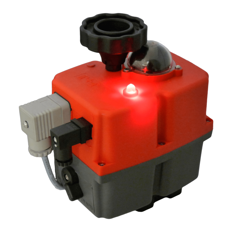
Advertisement
Available languages
Available languages
Quick Links
J3C S20/S85 KIT BSR 2015 ASSEMBLY INSTRUCTIONS
VERY IMPORTANT:
PLEASE, FOLLOW THESE INSTRUCTIONS STEP BY STEP.IF THE CONNECTOR OF THE BATTERY PACK IS PLUGED TO
THE "BSR" PCB, BEFORE ARRIVING TO POINT 9, THE PCB COULD BE DAMAGED.
INNER BOX
KIT COMPONENTS
A 1 BSR PCB
B 1 BSR PCB Fixing screw
C 1 Battery
D 1 Washer
E 1 Battery Fixing screw
1. Remove the cover of the actuator .
- Remove the hand wheel screws and take the hand wheel off. (fig. 1 & 2).
2. Remove the 6 screws between the cover and the body of the actuator.(fig.3).
3. Carefully remove the cover, in order to install the kit.(fig.4).
4. Remove the screw indicated in (fig.5).
5. Place the battery pack on the indicated position (fig.6).
6. Take the screw kit (E), put the washer (D) along the screw and introduce it in the battery (Fig.7.1 o 8.1). Fix the battery to the
base plate.
7. Place the battery cable, as per (fig.8).
8. Take the "BSR" PCB (A) from the KIT and connect it to the actuator PCB, by using the connectors marked with a circle. See
(fig.9).
9. Fix the "BSR" PCB to the base plate by using the screw (B). See (fig.10).
10. Plug the battery pack connector to the "BSR" PCB base connector, located on the top of this PCB (fig. 11).
11. BSR Configuration (fig. 12 jumper SELDIR): NC (normally close) jumper ON.
NO (normally open) jumper OFF.
12. Carefully replace the cover and be sure that the joint is correctly lodged in its place. See (fig.13). Be sure that any cable is not
trapped between the cover and the body.
13. Fix the 6 screws, between the cover to the body. See (fig. 14).
14. Reassemble the hand wheel and fix it with the screws. See (fig.15).
15. Put the hand wheel cover back and fix it with the screw. See (fig.16).
16. Fill in the blanks of the document inside the BSR KIT and send it back to the supplier, via fax or mail.
The actuator is ready to work.
We strongly recommend to put the power on, send the actuator to an intermediate position and check that , after putting the power
off, the actuator goes to the pervious set-up position (NC or NO).
DOCUMENT
TO COMPLETE
ASSEMBLY
INSTRUCTIONS
A
D
E
B
C
1
2
A
A
5
6
8
9
11
13
15
3
4
7
10
12
Jumper SELDIR
15
16
A
A
Advertisement

Summary of Contents for J3C S20
- Page 1 J3C S20/S85 KIT BSR 2015 ASSEMBLY INSTRUCTIONS VERY IMPORTANT: PLEASE, FOLLOW THESE INSTRUCTIONS STEP BY STEP.IF THE CONNECTOR OF THE BATTERY PACK IS PLUGED TO THE “BSR” PCB, BEFORE ARRIVING TO POINT 9, THE PCB COULD BE DAMAGED. DOCUMENT TO COMPLETE...
- Page 2 INSTRUCCIONES MONTAJE KIT BSR 2015 J3C S20/S85 KBJ3CSV001 AVISO MUY IMPORTANTE: SEGUIR PASO A PASO ESTAS INSTRUCCIONES. SI EL CONECTOR DE LA BATERIA ESTA CONECTADO A LA ELECTRONI- CA DEL BSR, ANTES DE LLEGAR AL PUNTO 10, LA ELECTRÓNICA PUEDE DAÑARSE.
