Table of Contents
Advertisement
Quick Links
Advertisement
Table of Contents

Related Manuals for Hammer HNC 47.82


Summary of Contents for Hammer HNC 47.82
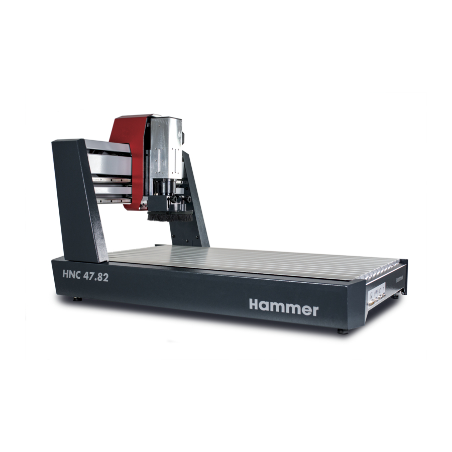
- Page 1 HNC 47.82 CNC portal machine Keep this manual to hand and in good condition for future reference! Please read this operating manual carefully before using the machine! Translation of the original operating instructions Version 1.3 9.6.2020 HNC_01, 4, en_GB...
- Page 2 Felder KG KR-Felder Straße 1 6060 Hall in Tirol +43 (0) 5223 / 5850 0 info@felder-group.com www.felder-group.com © 2020...
-
Page 3: Table Of Contents
HNC 47.82 Table of contents Table of contents Instructions ..............7 Symbol legend . - Page 4 Table of contents Packaging............26 Store .
- Page 5 HNC 47.82 Table of contents 11.4 Check/replace the drive belt..........52 11.5...
- Page 6 Table of contents...
-
Page 7: Instructions
HNC 47.82 Instructions Instructions Symbol legend Safety instructions Safety instructions in this manual are indicated with symbols. The safety instruc- tions are introduced by key words which state in words the extent of the hazard. Comply with safety instructions under all circumstances, and act with care in order to avoid accidents, personal injury, or material damage. -
Page 8: Copyright
Instructions Copyright This instruction manual is to be treated as confidential. It is intended solely for those people who are to work on or with the machine. All descriptions, texts, drawings, photos and other depictions are protected by copyright and other commercial laws. Any unauthorised use is prohibited. This manual, in its entirety or parts thereof, may not be transferred to third parties or copied in any way or form, and its contents may not be used or otherwise com- municated without the express written consent of the manufacturer. - Page 9 HNC 47.82 Instructions Note: The original spare parts that have been authorised for use are listed in a separate spare parts catalogue, enclosed in the docu- mentation package supplied with the machine.
-
Page 10: Security
Security Security At the time of its development and production, the machine was built in accord- ance with prevailing technological regulations and therefore conforms to industry safety standards. However, hazards may arise should the machine be operated by untrained personnel, used improperly or employed for purposes other than those it was designed for. -
Page 11: Making Changes And Modifications To The Machine
HNC 47.82 Security Making changes and modifications to the machine In order to minimise risks and to ensure optimal performance, it is strictly pro- hibited to alter, retrofit or modify the machine in any way without the express con- sent of the manufacturer. All the pictograms, signs and labels affixed to the machine must be kept visible, readable and may not be removed. -
Page 12: Work Safety
Security Work safety Following the safety advice and instructions given in this manual can prevent bodily injury and material damage while working on and with the machine. Failure to observe these instructions can lead to bodily injury and damage to or destruction of the machine. -
Page 13: Other Risks
HNC 47.82 Security WARNING Danger! Electric current! Electrical energy can cause serious bodily injury. Damaged insula- tion materials or defective individual components can cause a life- threatening electrical shock. ● Before carrying out any maintenance, cleaning and repair work, switch off the machine and ensure that it can not be accidentally switched on again. - Page 14 Security ● Spare parts, accessories and equipment that are not approved by the manu- facturer. Use only genuine spare parts supplied by the manufacturer. ● To change or modify the machine. ● To adapt, remove and bridge the safety equipment. During operation: ●...
-
Page 15: Declaration Of Conformity
HNC 47.82 Declaration of Conformity Declaration of Conformity EG-Declaration of Conformity according to Machine Guidelines 2006/42/EG Declaration of Conformity We hereby declare that the machine indicated below, which corresponds to the design and construction of the model we placed on the market, conforms with the health and safety requirements as stated by the EC guidelines (see table). -
Page 16: Technology Data
Technology Data Technology Data All technical information is for the standard equipment without spindle and extrac- tion hood. Machine: Dimensions and Data Value weight Total length 1111 mm Total width 762 mm Total height 682 mm Weight approx. 81 kg Packaging incl. - Page 17 HNC 47.82 Technology Data Inner dimensions of the Data Value portal & other dimensions Clearance width 625 mm Clearance height 160 mm Table surface 1005 mm x 574 mm T grooves in the table 17.5mm x 7.5 mm for M8 Tool chucks (standard) Ø...
- Page 18 Technology Data Electrical connections Fig. 2: Machine connections at the rear Main switch Mains connection C14 Rotation speed control (0-10 volts) (not with HF motors) Connection for the machine head (not with HF motors) Extraction/cable guides Fig. 3: Electrical control box HF Mains connection C14 Main switch...
- Page 19 HNC 47.82 Technology Data Data Value Connection point on the machine C14 device plug Input voltage machine 88-264 V AC 50/60 Hz Power consumption of the machine / 460 W / 2300W incl. accessories max Output voltage C13 device socket...
- Page 20 Technology Data Operation and storage Data Value conditions Operating/room temperature +10°C bis +40°C Relative max. humidity 60 % Warehouse temperature -10°C bis +50°C Dust extraction Data Value Diameter of the extraction connection 32 mm Air speed 20 m/s Volume flow (at 20 m/s) 60 m³/h Vacuum 20,000 Pa...
-
Page 21: Noise Emission
HNC 47.82 Technology Data X-axis Y-axis Z-axis Negative limit 0.00 0.00 0.00 Reference point 798.00 449.00 160.00 Noise emission See separate operating manual for the tool mounted. CAUTION High noise emission due to blunt tools and incorrect rotation speed Permanent hearing damage −... -
Page 22: Machine Assembly
Mains connection & main switch Portal with machine head Clamping of the router Connections Machine data plate A-6060 HALL in Tirol, KR-Felder-Straße 1 Austria, Tel. +43 (0) 5223 58500 Fax +43 (0) 5223 56130, info@hammer.at www.hammer.at TYPE: HNC 47.82 Nr.: 534-00x-xxx V:230.0... -
Page 23: Safety Devices
HNC 47.82 Machine assembly Safety devices ● The machine is equipped with an emergency stop button. This must be con- nected to the machine. See ‘Connection emergency stop’ on page 33 ● The use of an extraction protection hood is compulsory when using rotating tools. -
Page 24: Transport, Packaging And Storage
Transport, packaging and storage Transport, packaging and storage Safety instructions NOTICE Transport damage The machine can be damaged or destroyed if it is subjected to improper handling during transport. − Always move the machine with the utmost care and caution. −... -
Page 25: Transport
HNC 47.82 Transport, packaging and storage Transport Fig. 8: Packaging The machine is transported equipped with the transport locks. It is recommended to store the packaging and transport locks, once removed. If, due to any defects, the machine has to be returned to the manufacturer then the original packaging and transport locks should be used. -
Page 26: Packaging
Transport, packaging and storage Packaging If no agreement has been made with the supplier to take back the packaging materials, help to protect the environment by reusing the materials or separating them according to type and size for recycling. Environmental protection Packaging materials are valuable raw materials and in many cases they can be used again, reprocessed or recycled. -
Page 27: Setup And Installation
HNC 47.82 Setup and installation Setup and installation Safety instructions WARNING Improper setup and installation Severe injuries and damage to property − Work may only be carried out by authorised, trained per- sonnel who are familiar with how to operate the machine and are in strict observance of all safety instructions. -
Page 28: Remove Transport Locking Devices
Setup and installation Remove transport locking devices It is recommended to store the packaging and transport locks, once removed. If, due to any defects, the machine has to be returned to the manufacturer then the original packaging and transport locks should be used. Fig. -
Page 29: Setup
HNC 47.82 Setup and installation Setup Requirements ● Operating/room temperature: +10°C bis +40°C ● Sufficiently stable and proper load-bearing capacity of the work surface. Instable work surfaces create safety risks. And they can also lead to stop- page of the machine. -
Page 30: Mount The Extraction Hood
Setup and installation Mount the extraction hood Fig. 11: Mount the extraction hood Extraction hood Height adjustment screw Mount for the height adjustment screw Magnetic dust brush Mount the extraction hood to the machine head using the height adjustment screws. Mount the magnetic dust brush to the extraction hood. -
Page 31: Electrical Connection
It is prohibited to open the electrical box on the machine without the express authorization from the Hammer Service Department. Violating this stipulation renders any guarantee rights invalid. Before connecting the machine to the power supply, compare the information on the nameplate with those of the power supply. - Page 32 Setup and installation 4th axis AUX-Port Fig. 13: Machine connections at the rear Main switch Mains connection C14 Rotation speed control (0-10 volts) (not with HF motors) Connection for the machine head (not with HF motors) Extraction/cable guides Mains connection machine Connect the machine using the C13 plug at the rear of the machine to the power supply.
- Page 33 HNC 47.82 Setup and installation Mains connection HF spindle (optional) Fig. 14: Electrical control box HF Mains connection C14 Main switch The HF spindle is premounted and connected to the machine. The frequency inverter must be placed on a flat, stable surface and connected to the mains supply ( ...
-
Page 34: Software
Setup and installation Connect the controller to the PC using the USB cable. Software Download / Installation Download the Eding CNC Software and instruction manual from the manu- facturer ( https://www.edingcnc.com/). Install the Eding CNC software on to the PC following the manufacturers instruction manual. -
Page 35: Adjustments And Tool Changes
HNC 47.82 Adjustments and tool changes Adjustments and tool changes Safety instructions WARNING Improper adjustment and setup Serious physical injury or material damage. − Adjustment and setup may only be carried out by authorised, trained personnel who are familiar with how to operate the machine and are in strict observance of all safety instructions. -
Page 36: Tighten The Router Motor In Place
Adjustments and tool changes Tighten the router motor in place Fig. 17: Tighten the router motor in place Fixation of the router motor Mains connection router motor (rear side) Extraction/cable guides Place the router motor in to the 43 mm collar and clamp using the nut (10-11 Nm). -
Page 37: Tighten The Router Tool In Place
In order to ensure that the machine can be worked with safely, the protective housing must be used. This housing must completely encompass the machine, on all four sides (length and width). HAMMER machine manufacturing recommends using MDF panels with a thickness of 19 mm. -
Page 38: Hf-Motor (Optional)
Adjustments and tool changes Fig. 18: Protective housing All-round protective housing Dimensions Length 1500 mm Width 1000 mm Height 800 mm Material MDF, 19 mm 9.3.2 HF-motor (optional) WARNING Collision danger and risk of cutting Severe injuries caused by rotating tools −... - Page 39 HNC 47.82 Adjustments and tool changes WARNING Hand injuries Risk of injury due to sharp or hot tools − Adjustments to the machine or changing the tools may only be done once the machine has stopped. − Wear protective gloves. Tools can become hot when being used.
-
Page 40: Router Motor Hfm 1000
Adjustments and tool changes Then tighten the spindle with the respective spanner (22 mm). Tighten the locking nut and check that the router tool is inserted correctly. CAUTION Caution! Personal damage! Router tools must always be mounted using the respective oper- ating tools and with the correct torque. - Page 41 HNC 47.82 Adjustments and tool changes ● Check before running for the first time, or after any significant changes that the air speed complies with the requirements. ● The dust extraction setup must be checked before the machine is put into operation for the first time.
-
Page 42: Operation
Operation 10 Operation WARNING Insufficient preparation Severe injuries and damage to property − It is only permitted to switch on the machine if, for the work at hand, the required preconditions are fulfilled and any prelimi- nary work is completed. −... -
Page 43: Preparation
HNC 47.82 Operation During operation ● When changing to another workpiece or if a malfunction occurs, first switch off the machine and then secure it against being switched on again acciden- tally. ● Do not switch off, circumvent or remove protective and safety devices during operation. -
Page 44: Operation Of The Machine
Operation 10.3 Operation of the machine Loading CAM programs in the operation software. Fixing workpieces to the machine table using clamping devices. Use martyr panels if necessary (e.g. when through routing). Use clamping devices according to the manufacturers manual. Move to the workpiece zero point (see software instructions). Zero the axes to the workpiece (X and Y). -
Page 45: Process Accuracy
HNC 47.82 Operation 10.4 Process accuracy 10.4.1 Workpiece If the workpiece is bowed, then clamp it with the bow facing upwards. If locking holes are drilled for groove nuts, then they have to be chosen in such a way, that the bow will be optimally compensated against. -
Page 46: Maintenance
Maintenance 11 Maintenance 11.1 Safety instructions WARNING Improper maintenance Severe injuries and damage to property − Maintenance work may only be carried out by authorised, trained personnel who are familiar with how to operate the machine and are in strict observance of all safety instructions. ●... -
Page 47: Maintenance Schedule
HNC 47.82 Maintenance ● Constant line of sight between the operator and maintenance technician in order to ensure clear and quick communication. ● Instructions given by the technician must be repeated and confirmed by the operator before they are carried out. - Page 48 Maintenance Y-axis Fig. 22: Lubricate the Y-axis Spindle The Y axis spindle is easy to access. Lubricate the spindle using a paintbrush and grease. SHELL Gadus S3 V220C lubricate. X-axis Fig. 23: Tilt the machine up in the direction of the machine head...
- Page 49 HNC 47.82 Maintenance Fig. 24: Lubrication of the X axis Trapezoidal spindle Carry out reference run. Switch the machine off and ensure that it cannot be switched on again. Tilt the machine on the side on which the machine head is situated.
- Page 50 Maintenance Z-axis Fig. 25: Remove the Z-axis cover Spindle holder Remove the cover screws...
- Page 51 HNC 47.82 Maintenance Cable guide Z-axis cover Fig. 26: Lubricate Z-axis Z-axis Move the Z-axis into the highest position. Disconnect the machine from the power supply. Remove the router motor and extraction. Unscrew the spindle holder. Loosen both cover screws.
-
Page 52: Check/Replace The Drive Belt
Maintenance Move the cover upwards and away. Move the Z-axis downwards on the drive wheel of the belt. Lubricate the spindle using a paintbrush and grease. SHELL Gadus S3 V220C lubricate. Move the Z-axis upwards on the drive wheel of the belt. Put everything back together in reverse order. - Page 53 HNC 47.82 Maintenance Loosen the 4 motor fixing screws (do not remove them). Support the oppo- site side. Remove the old belt and dispose of correctly. Fitting a new belt. To tighten the belt, move the motor with one hand away from the axis and then lock in place using the locking screws.
- Page 54 Maintenance Y-axis Fig. 28: Screws for the side cover Screws for the side cover...
- Page 55 HNC 47.82 Maintenance Fig. 29: Y-axis belt change Screws for the portal cover (both sides) Portal cover Locking screws (4x) Drive belt Remove the side cover screws (both sides of the portal). Unscrew the portal cover on both sides. Remove the cover.
- Page 56 Maintenance X-axis Fig. 30: Underside of the HNC Remove the cover screws Wheels Belt tensioner Fig. 31: Remove the front and rear cover Cover screws...
-
Page 57: Check Protective Equipment
Screw the cover back on and remove the clamps on the portal. 11.5 Check protective equipment Check the emergency stop Press the emergency stop whilst the machine is running. regularly The machine will stop automatically. In the event of a malfunction please contact Hammer service. -
Page 58: Faults
Faults 12 Faults 12.1 Safety instructions WARNING Risk of injury! Repairing faults incorrectly can result in personal injury or damage to the machine. For this reason, this work may only be carried out by authorised, trained personnel who are familiar with how to operate the machine and in strict observance of all safety instruc- tions. - Page 59 HNC 47.82 Faults Fault Cause Repair Main switched off (setting "0") Switch on the main switch ("I" position) Emergency stop is pressed Unlock emergency stop Emergency stop is not connected Connect emergency stop to the to the machine machine Axis are not moving, but the step The drive belt is broken.
-
Page 60: Disposal
Disposal 13 Disposal Before disposing of the machine, contact the manufacturer. Should the machine be disposed of at the end of its operating life, all of the com- ponents need to be separated according to material class, to enable recycling or scrapping. - Page 62 Felder KG KR-Felder Straße 1 6060 Hall in Tirol +43 (0) 5223 / 5850 0 info@felder-group.com www.felder-group.com...
Need help?
Do you have a question about the HNC 47.82 and is the answer not in the manual?
Questions and answers