Table of Contents
Advertisement
Advertisement
Table of Contents

Summary of Contents for Baur SSG 1100
- Page 1 User manual Surge Voltage Generator SSG 1100 SSG 1500 SSG 2100 SSG 3000 Ident. Nr. 822-017 02/2014 BAUR Prüf- und Messtechnik GmbH e-mail: headoffice@baur.at Tel. +43/5522/4941-0 Raiffeisenstrasse 8, A-6832 Sulz/Austria internet: www.baur.at Fax +43/5522/4941-3...
- Page 3 Important information about the instrument! In any case, read carefully! Important information text. Copyright © BAUR Prüf- und Messtechnik GmbH, A-6832- Sulz / Austria All rights reserved. No part of this publication may be reproduced, transmitted, stored in a data processing system or translated into another language without the written permission of BAUR / Sulz, Austria.
- Page 4 The warranty does not cover damage in transit, batteries, fuses and any readjustments in accordance with the Operating Instructions! We draw attention in addition to the ‘General Sales and Business Conditions’ of: BAUR Prüf- und Messtechnik Gmbh Raiffeisenstrasse 8, A-6832-Sulz / Austria...
-
Page 5: Table Of Contents
Breakdown voltage of spark gap ................ 20 4.4 Checking the discharge unit ................21 4.5 Replacing high voltage connecting lead ............21 5 Options, Accessories and Ordering Information ..........22 5.1 Options ........................22 5.2 Accessories ......................22 5.3 Ordering information SSG 1100 ................23 ... -
Page 6: Product Information
Function The Surge Voltage Generators SSG 1100, SSG 1500, SSG 2100 and SSG 3000 are designed in such a way that they generate pulse-shaped voltages with a steep edge, which should start to break down the cable fault. -
Page 7: Display And Operating Elements
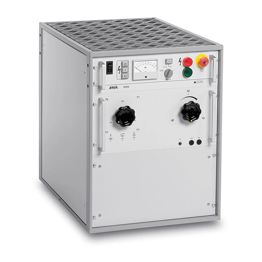
1.2 Display and operating elements Front panel 1 Mains switch as overload protection switch with thermal tripping 2 Push button switch „Ready to switch on“ ( 3 Push button switch „H.V. On“ ( I ) with indicator lamp for high voltage clearance. The indicator lamp serves as feedback for the operating state „IN OPERATION“... - Page 8 16 Connection socket for external EMERGENCY OFF unit with jumper plug 17 Connection for mains to SA 32 18 Connection for mains 19 Terminal for connection of protective earth lead 20 Spark gap 21 Shorting bar for bridging the spark gap during D.C. operation 22 Knurled nut for H.V.
-
Page 9: Technical Data
1.3 Technical data Unit 1100 1500 2100 3000 Mains voltage see type plate Mains frequency 45 to 60 45 to 60 45 to 60 45 to 60 Max. power consumption (at short circuit condition) 3000 5000 5000 5000 Max. output voltage Max. -
Page 10: Packing And Shipping
If damage is discovered during unpacking, contact the responsible transportation company immediately. Request a written loss assessment and make them responsible for the damage! We also refer to the “General Terms of Sale and Delivery„ of: BAUR Prüf- und Messtechnik GmbH A-6832 Sulz/Austria... -
Page 11: Placing Into Operation
Automatic impulse triggering is primarily used for pin-pointing a cable fault. The SSG 1100, SSG 1500 and SSG 2100 are equipped with a timer coupled to the mains frequency which allows for automatic impulse triggering with impulse frequencies of 10/min and 20/min. - Page 12 (14). During short term operation, maximum output currents can be found during the burn down process according to the following table. max. output current (IMAX) Range selector switch SSG 1100 SSG 1500 SSG 2100 SSG 3000 in 8 kV position...
-
Page 13: Connection Of Instrument
3.2 Connection of instrument Observe correct position of connection terminals! (also see Note on page 14) Connection to a single-phase shielded cable Connection of a three-phase shielded cable Connection to a three-phase unshielded cable with neutral Rear view of device - Protective ground connection 2. - Page 14 Preparing test object Isolate the test object Lock against reconnection Make sure that zero voltage condition exists. Insulate nearby items which are under voltage It must be assured that nearby items of the station or cable system under voltage do not result in breakovers or breakdowns, due to applying surge or D.C.
-
Page 15: Connection To Mains
Estabilshing H.V. connection Connect strand of the high voltage connecting lead with the fault afflicted strand of the test object. It is very important that all connections are of low resistance as possible. Bad connections can lead to weldings or contact wear. At the instrument, protective earth and station earth may not be connected with each other. -
Page 16: Switch On
3.4 Switch on Danger! High-voltage When using surge mode: Cordon off surge voltage generator at a distance of 1.5 m Persons must stand only outside the barrier Turn variable transformer (11) to its left position. Set range selector switch (15) to the desired range 8 /16 /32 kV. ... -
Page 17: Switch Off
Live parts must be discharged, earthed and shorted. The Surge Voltage Generators SSG 1100, SSG 1500, SSG 2100 and SSG 3000 features an internal discharge unit with separated discharge of surge capacitors and test object capacity, but not an internal earthing unit. -
Page 18: Emergency Switching Off
3.7 EMERGENCY SWITCHING OFF Press EMERGENCY OFF pushbutton switch (11). The instrument returns to the operating condition „READY FOR OPERATION“. The high voltage transformer will be isolated from the supply voltage. → the indicator lamp „IN OPERATION“ of pushbutton switch (3) is out →... -
Page 19: Servicing / Maintenance
4 Servicing / Maintenance 4.1 Safety precautions The Surge Voltage Generators SSG 1100, SSG 1500, SSG 2100 and SSG 3000 have a surge capacitor available which consists of four isolated partial capacitors. Even in the turned off condition these partial capacitors can show substantial residual charges. For safety reasons,... -
Page 20: Breakdown Voltage Of Spark Gap
3,15 AT Ø 5 x 20 mm 563-021 Lifting magnet control and control of SA 32 (S4, F10) 16 AT Mains switch (1) F11 SSG 1100 6 AT High voltage transformer, (220-240V) primary (12) F11 SSG 1100 12AT High voltage transformer,... -
Page 21: Checking The Discharge Unit
First install station earth (blue) on instrument side and tighten knurled nut (23). Subsequently, install H.V. connection and tighten knurled nut (22). Use only the original BAUR H.V. connecting lead suitable for the particular instrument. When replacing parts, check if the accessible mounting screws for the electrode support (25) are tightened. -
Page 22: Options, Accessories And Ordering Information
5 Options, Accessories and Ordering Information 5.1 Options Intercom SA 32 The primary application of the Intercom SA 32 is as „aid“ for prelocating of cable faults. It allows locating of high-resistance faults utilizing the secondary impulse method (SIM). This allows for transformation of high-resistance faults into low resistance faults. The surge voltage impulse of the SSG is consequently led to the test object via the high-performance resistors. -
Page 23: Ordering Information Ssg 1100
5.3 Ordering information SSG 1100 Items included Surge voltage generat. SSG 1100 without accessories Power card ² Ground line 10 mm ; 4 m Jumper plug ext. EMERGENCY OFF Options 19" - housing 14 HE 700, without carrying handles 19" - housing 17 HE 700, without carrying handles 1 pair of handles for 19"... - Page 24 Ordering information SSG 1500 Items included Surge voltage generat. SSG 1500 without accessories Power card ² Ground line 10 mm ; 4 m Jumper plug ext. EMERGENCY OFF Options 19" - housing 14 HE 700, without carrying handles 19" - housing 17 HE 700, without carrying handles 1 pair of handles for 19"...
- Page 25 Ordering information SSG 2100 Items included Surge voltage generat. SSG 2100 without accessories Power card ² Ground line 10 mm ; 4 m Jumper plug ext. EMERGENCY OFF Options 19" - housing 14 HE 700, without carrying handles 19" - housing 17 HE 700, without carrying handles 1 pair of handles for 19"...
- Page 26 EMERG. OFF unit with warning lamps on drum, 25m EMERG. OFF unit with warning lamps on drum, 50m Intercom SA 32 LV surge capacitor bank SZ 1000 LV surge capacitor bank SZ 1600 BAUR Prüf- und Messtechnik GmbH A-6832 Sulz/Austria...