Vmac Underhood 40 Installation Manual
For 2014+ ford transit connect
Hide thumbs
Also See for Underhood 40:
- Installation manual (80 pages) ,
- Owner's manual (60 pages) ,
- Installation manual (64 pages)

Subscribe to Our Youtube Channel
Related Manuals for Vmac Underhood 40


Summary of Contents for Vmac Underhood 40
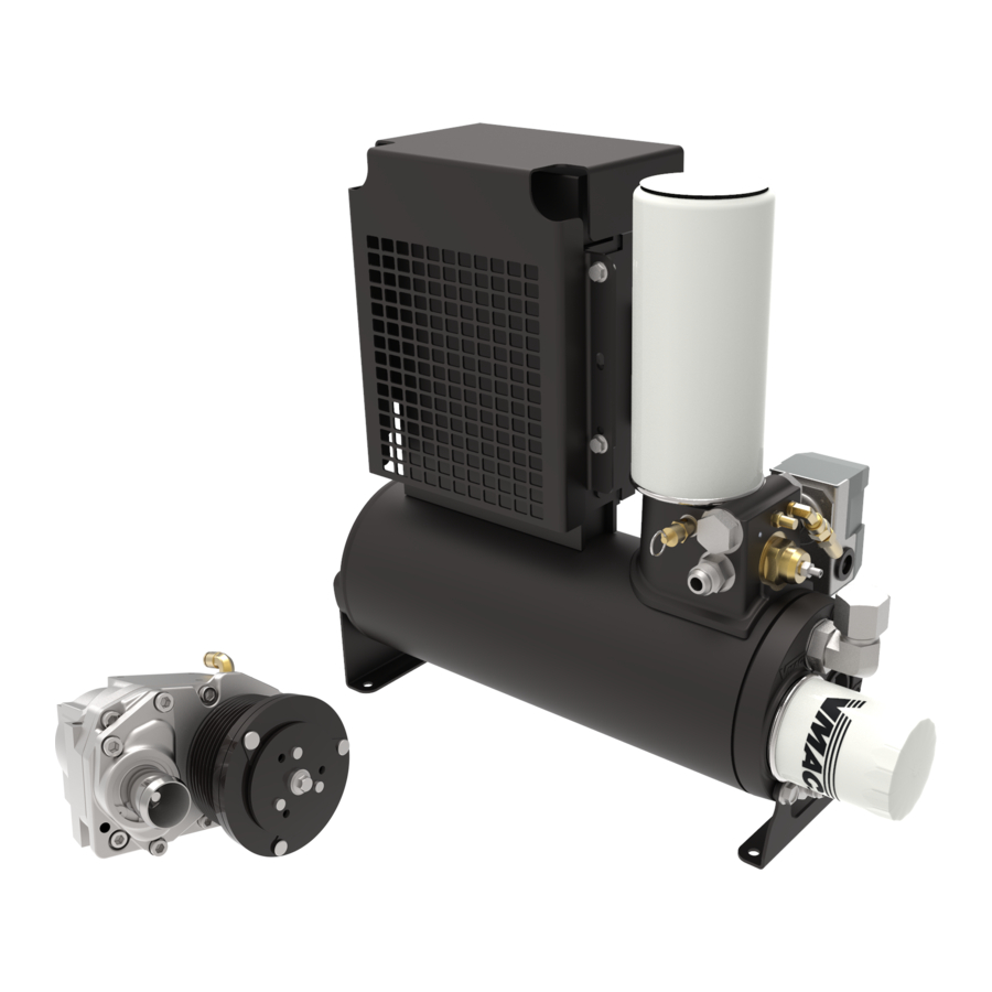
- Page 1 Installation Manual for VMAC System V400008 2014 + Ford Transit Connect 2.5 L Gas (L4) www.vmacair.com www.vmacair.com...
-
Page 3: Table Of Contents
Accessory Products from VMAC ........ - Page 4 Copyright © 2020 VMAC Global Technology Inc. All Rights Reserved. These materials are provided by VMAC for informational purposes only, without representation or warranty of any kind, and VMAC shall not be liable for errors or omissions with respect to the materials. The only warranties for VMAC...
-
Page 5: Safety
VMAC will not be held responsible for any liability, consequential damages, injuries, loss or damage to individuals or to equipment as a result of the failure of anyone to properly adhere to the procedures set out in this manual or standard safety practices. -
Page 6: Warranty
1 October, 2015. Warranty Registration The VMAC warranty registration form is located near the back of this manual. This warranty registration form must be completed and sent to VMAC at the time of installation for any subsequent warranty claim to be considered valid. - Page 7 2. VMAC will provide direction for repair or replacement of the failed components. 3. If requested, failed parts must be returned to VMAC for evaluation. 4. Dealers may login to the VMAC website to view the "VMAC Labour Time Guide" (under “Agreements”) to see the allowable warranty labour times.
-
Page 8: General Information
Please contact VMAC for replacement hoses and further information. Ordering Parts To order parts, contact a VMAC dealer. The dealer will ask for the VMAC serial number, part number, description and quantity. Locate the nearest dealer online at www.vmacair.com/dealer-locator or call 1-877-912-6605. - Page 9 All fasteners must be torqued to specifications. Use manufacturers’ torque values for OEM fasteners. The torque values supplied in Table 1 are intended for VMAC supplied components, or for use as a guide in the absence of a torque value provided by an OEM.
-
Page 10: System Identification, Warranty Registration And Warning Labels
☐ Complete the warranty form. The VMAC warranty form is located at the back of this manual, as well as online at: www.vmacair.com/warranty The System Identification Plate must be attached to the vehicle at the time of installation. - Page 11 To alert any technicians that may service the vehicle, affix the servicing caution/contact label in the engine compartment near the hood latch in a visible location (Figure 3). Figure 3 — Advisory label VMAC - Vehicle Mounted Air Compressors VMAC Technical Support: 888-241-2289 VMAC Knowledge Base: kb.vmacair.com...
-
Page 12: Preparing For Installation
Due to variations in service body design and other equipment, VMAC cannot specify a mounting location for the WHASP tank. This VMAC kit includes 36 in of hose to run from the bulkhead fittings to the WHASP tank. If your application requires longer hoses, refer to “Hose Requirements”... - Page 13 Move the gear selector to the “S” position. ☐ Remove the kick panel below the steering column (Figure 6). Figure 6 — Remove steering column kick panel VMAC - Vehicle Mounted Air Compressors VMAC Technical Support: 888-241-2289 VMAC Knowledge Base: kb.vmacair.com...
- Page 14 Remove the fasteners securing the checkered dashboard insert, starting from the steering column, and moving towards the glove box (Figure 8). Figure 8 — Remove dashboard insert VMAC - Vehicle Mounted Air Compressors VMAC Technical Support: 888-241-2289 VMAC Knowledge Base: kb.vmacair.com...
- Page 15 Figure 9 — Remove dashboard insert ☐ Remove the push fasteners from both sides of the lower dashboard panel (Figure 10). Remove push fasteners Figure 10 — Remove lower dashboard VMAC - Vehicle Mounted Air Compressors VMAC Technical Support: 888-241-2289 VMAC Knowledge Base: kb.vmacair.com...
- Page 16 Remove the doorsill trim panel. Steering column cover ☐ Remove the lower steering column cover (Figure 12). Remove steering column cover Figure 12 — Remove steering column cover VMAC - Vehicle Mounted Air Compressors VMAC Technical Support: 888-241-2289 VMAC Knowledge Base: kb.vmacair.com...
- Page 17 Figure 13 — OEM Tensioner ☐ Remove and discard the OEM ‘back” idler. The idler has an M6 bolt (Figure 14). OEM “back” idler Figure 14 — OEM Back Idler VMAC - Vehicle Mounted Air Compressors VMAC Technical Support: 888-241-2289 VMAC Knowledge Base: kb.vmacair.com...
-
Page 18: Installing The Main Bracket, Compressor, And Drive Belts
Connecting the Crank Position Sensor (CKP) The Throttle Control connections to the Crank Position (CKP) sensor should be made prior to installing the VMAC main bracket as this provides the most unobstructed access. The remainder of the electrical connections will be covered later in this manual. - Page 19 *White wire from the Throttle Control to the yellow/violet wire (PIN 1) CKP. ☐ *Blue wire from the Throttle Control to the green/brown wire (PIN 2) CKP. VMAC - Vehicle Mounted Air Compressors VMAC Technical Support: 888-241-2289 VMAC Knowledge Base: kb.vmacair.com...
- Page 20 Installing the VMAC Main Bracket ☐ If equipped, remove the engine lifting eye. ☐ Install the VMAC idler (from the fast pack) in the OEM “back” idler position and torque to specification (Figure 18). Spacer Idler Spacer Bolt (P/N: 1400414)
- Page 21 “valley” in the valve cover (Figure 20). Remove push fastener Figure 20 — Reroute harness ☐ Install the VMAC main bracket onto the engine and torque to specification (Figure 21). Main bracket mount location Figure 21 — Main bracket installation...
- Page 22 Figure 23 — Secure Coolant Hose ☐ Install the tensioner on the main bracket (Figure 24). VMAC tensioner Bolt (P/N: 1520552) Figure 24 — Mount tensioner VMAC - Vehicle Mounted Air Compressors VMAC Technical Support: 888-241-2289 VMAC Knowledge Base: kb.vmacair.com...
- Page 23 Compressor mounts Figure 25 — Mount compressor ☐ Install the VMAC belt on the inside track of the crank pulley. Two clutch ribs should be visible on each side of the belt (Figure 26). Two ribs visible on each side Figure 26 —...
- Page 24 Install the P-clip bracket using the supplied Phillips head cap screws (Figure 28). M6 × 12 mm M5 × 10 mm screw screw Passenger side Figure 28 — P-clip bracket VMAC - Vehicle Mounted Air Compressors VMAC Technical Support: 888-241-2289 VMAC Knowledge Base: kb.vmacair.com...
-
Page 25: Installing The Bulkhead Fittings
WHASP Tank. Also ensure that there are no wires, hoses, or other components on the other side of the panel that may be damaged when drilling holes. VMAC - Vehicle Mounted Air Compressors VMAC Technical Support: 888-241-2289 VMAC Knowledge Base: kb.vmacair.com... - Page 26 Figure 30 — Remove plastic step ☐ Remove the plastic step to provide access to the sub floor (Figure 31). Figure 31 — Access the sub floor VMAC - Vehicle Mounted Air Compressors VMAC Technical Support: 888-241-2289 VMAC Knowledge Base: kb.vmacair.com...
- Page 27 Install the bulkhead fittings in the floor tunnel. These instructions are continued on the next page (Figure 33). Locate the bulkhead fittings in the floor tunnel Figure 33 — Floor tunnel VMAC - Vehicle Mounted Air Compressors VMAC Technical Support: 888-241-2289 VMAC Knowledge Base: kb.vmacair.com...
- Page 28 Front of vehicle ø 9/16 in Driver side of vehicle ø 5/8 in ø 5/8 in ø 1 1/8 in Figure 34 — Vehicle chassis (bottom view) VMAC - Vehicle Mounted Air Compressors VMAC Technical Support: 888-241-2289 VMAC Knowledge Base: kb.vmacair.com...
- Page 29 Figure 35 — Bulkhead fittings (bottom view) Figure 36 — Bulkhead fittings (top view) VMAC includes bulkhead fittings to connect the hoses from the engine compartment to the interior of the van. While it is necessary to provide a secure transition from the sub floor to the cargo bay, individual layout designs preclude VMAC from recommending specific bulkhead fixtures.
-
Page 30: Hose Requirements
They can be shortened or replaced as necessary, or hose extenders can be used. In the event that the hoses are too long, VMAC recommends shortening these hoses as a preferred alternative to coiling up and securing the excess. -
Page 31: Connecting The Hoses
Slide the collet out once proper tubing cutters as side cutters the tube is fully inserted will deform the tube. O-ring Figure 37 — Push-to-connect fittings VMAC - Vehicle Mounted Air Compressors VMAC Technical Support: 888-241-2289 VMAC Knowledge Base: kb.vmacair.com... - Page 32 Route the hoses over the top of the cross member and along the floor tunnel (Figure 39). Route hose over cross member Figure 39 — Hose routing VMAC - Vehicle Mounted Air Compressors VMAC Technical Support: 888-241-2289 VMAC Knowledge Base: kb.vmacair.com...
- Page 33 P-clip (Figure 41). P-clip attached to P-clip bracket Loom hoses prior to routing. Bundle hoses together using cable ties Figure 41 — Install Hoses VMAC - Vehicle Mounted Air Compressors VMAC Technical Support: 888-241-2289 VMAC Knowledge Base: kb.vmacair.com...
-
Page 34: Installing The Waste Heat Air Separator Package (Whasp) Tank
Illustrated Parts List (IPL). If the WHASP Tank or bulkhead fitting location requires longer hoses, contact a local VMAC dealer. See page 6 for ordering information . VMAC - Vehicle Mounted Air Compressors VMAC Technical Support: 888-241-2289... - Page 35 18 1/8 in 15 3/8 in 4 1/2 in 5/16 in or M8 mounting holes Figure 42 — Minimum WHASP Tank mounting clearances VMAC - Vehicle Mounted Air Compressors VMAC Technical Support: 888-241-2289 VMAC Knowledge Base: kb.vmacair.com...
- Page 36 (Figure 44). Front of vehicle Provide a minimum of 6 in of clearance for air flow Figure 44 — WHASP ventilation VMAC - Vehicle Mounted Air Compressors VMAC Technical Support: 888-241-2289 VMAC Knowledge Base: kb.vmacair.com...
- Page 37 Use of an air receiver tank (minimum 6 USG) is required with this application. Follow the instructions on page 48 of this manual to prevent damage to the system. VMAC - Vehicle Mounted Air Compressors VMAC Technical Support: 888-241-2289 VMAC Knowledge Base: kb.vmacair.com...
- Page 38 (Figure 47). Install push-to- connect fitting Figure 47 — Install push-to-connect fitting VMAC - Vehicle Mounted Air Compressors VMAC Technical Support: 888-241-2289 VMAC Knowledge Base: kb.vmacair.com...
- Page 39 Install the tube into the push-to-connect bulkhead fitting (Figure 49) Figure 49 — Tubing Installation Remote Blowdown Muffler assembly ☐ Secure the tube with the supplied cable ties. VMAC - Vehicle Mounted Air Compressors VMAC Technical Support: 888-241-2289 VMAC Knowledge Base: kb.vmacair.com...
-
Page 40: Adding Oil To The System
Adding Oil to the System The VMAC supplied and approved compressor oil must be used in this system. Failure to use this special oil will result in damage to the compressor and will void warranty. Do not overfill the system. Overfilling the system with oil can flood the sight glass window and make the system appear empty. -
Page 41: Installing The Control System
Strip the wire at the desired location and solder the VMAC wire into place. Slide the shrink tube up to the soldered joint and seal it. Finally, replace the pin in the connector, taking special care to ensure the pin is fully inserted and the locking tabs are engaged. - Page 42 Control Components Overview Compressor Control Module Throttle Control WHASP Interface Tank Panel Figure 53 — General component overview (Actual installation locations may vary) VMAC - Vehicle Mounted Air Compressors VMAC Technical Support: 888-241-2289 VMAC Knowledge Base: kb.vmacair.com...
- Page 43 Control Module (Figure 54) The Control Module serves as the primary input/output interface between the vehicle and the various VMAC components (compressor, Throttle Control, WHASP Tank, Control Interface, etc.). Power, 12 V Clutch, Throttle WHASP Compressor (switched), and Control, and...
- Page 44 “SPEED1” adjusting screw (under side) Figure 56 — VMAC Throttle Controls Mechanical Pressure Switch (Figure 57) The mechanical pressure switch is mounted on the side of the WHASP Tank and limits the maximum pressure to a safe amount by disengaging the clutch once system pressure is achieved.
- Page 45 Figure 58 — Electrical schematic VMAC - Vehicle Mounted Air Compressors VMAC Technical Support: 888-241-2289 VMAC Knowledge Base: kb.vmacair.com...
- Page 46 Grey cable Grey cable Figure 59 — Wire schematic VMAC - Vehicle Mounted Air Compressors VMAC Technical Support: 888-241-2289 VMAC Knowledge Base: kb.vmacair.com...
- Page 47 Throttle Control to the white/brown wire at pin 10 on the harness. Plug the connector back into the gear selector (Figure 61). Disconnect harness Figure 61 — Park interlock wire VMAC - Vehicle Mounted Air Compressors VMAC Technical Support: 888-241-2289 VMAC Knowledge Base: kb.vmacair.com...
- Page 48 Ensure the fuse holder is installed as close to the power source as possible. ☐ Connect the other end of the fuse holder to the positive battery terminal. VMAC - Vehicle Mounted Air Compressors VMAC Technical Support: 888-241-2289 VMAC Knowledge Base: kb.vmacair.com...
- Page 49 ☐ Ensure all wires and harnesses are protected with loom and routed away from sharp, hot, or moving components and away from high traffic areas. VMAC - Vehicle Mounted Air Compressors VMAC Technical Support: 888-241-2289 VMAC Knowledge Base: kb.vmacair.com...
-
Page 50: Air Receiver Tank
This is normal operation. Prior to performing any service work on the system, discharge any stored air in the air receiver tank. The VMAC WHASP Tank has a built-in check valve. Use of an additional check valve is not required and may cause erratic performance. -
Page 51: Recommended Accessories
Recommended Accessories While the compressor system will function without the following accessories, VMAC strongly recommends their use for optimal performance. See the “Accessory Product” section of this manual on page 56 for a list of products available for purchase through VMAC. -
Page 52: Completing The Installation
Completing the Installation ☐ Check all VMAC and OEM wiring to ensure that it will not contact any hot, sharp or moving components and will not interfere with the operation of the vehicle. Secure all wiring with rubber coated P-clips, cable ties and loom as required. -
Page 53: Testing The Installation
If the vehicle fails the test, ensure the wiring to all of the connections are correct and secure. If additional assistance is required, contact your local VMAC dealer or call VMAC Technical Support 1-888-241-2289 or 250-740-3200. Safety Test Ensure the following has been completed: ☐... - Page 54 The second person will actuate the compressor switch and ball valve as necessary ☐ Install the VMAC Air Test Tool (P/N: A700052) with the 40 cfm (5/32 in) orifice installed and the ball valve closed. ☐ With the engine running and the vehicle in “PARK”, release the parking brake.
- Page 55 Ensure the following has been completed: ☐ Operate the system with an air tool (or the VMAC Air Test Tool with the appropriate orifice installed) for at least 1/2 hour (1 hour preferred). The WHASP Tank cooling fan is thermostatically controlled, and may start or stop without warning.
-
Page 56: Performance Testing And System Adjustments
Try turning the engine speed down and observe the performance. When testing the system or adjusting the VMAC Throttle Control, ensure the system does not exceed 3,200 engine rpm. Exceeding this speed will cause erratic system performance and in extreme cases may also cause long term damage to the compressor. - Page 57 Control. System operation can be tested using the tools that will be operated by the system or by using the VMAC Test Tool (A700052) with the 40 cfm (5/32 in) orifice in the outlet to simulate tool use (Figure 66).
-
Page 58: Accessory Products From Vmac
Compressor Service Kits 200 Hour or 6 Month Service Kit - Part number: A700263 Includes 4 L VMAC high performance compressor oil, oil filter, air filter, and next service due decal. 400 Hour or 1-Year Service Kit - Part number: A700264... - Page 59 Air receiver tanks are used for lowering compressor duty cycle and removing water from compressed air; recommended for optimum operation of all VMAC Gas Driven, Diesel Driven, Hydraulic, and UNDERHOOD40 air compressors. Manufactured to FMVSS 121 standard; includes fittings, 160 psi pressure relief valve, and tank drain.
- Page 60 Interface Harness Extension Part number: A700265 This interface harness extension provides an additional 10 ft of cable which allows for greater flexibility in locating the Interface Panel. VMAC - Vehicle Mounted Air Compressors VMAC Technical Support: 888-241-2289 VMAC Knowledge Base: kb.vmacair.com...
- Page 61 Notes VMAC - Vehicle Mounted Air Compressors VMAC Technical Support: 888-241-2289 VMAC Knowledge Base: kb.vmacair.com...
-
Page 62: Warranty Registration
Warranty Registration This form must be fully completed and returned to VMAC at the time the vehicle is put into service. Warranty may be void if this form is not received by VMAC within 3 months of receiving the vehicle, or 200 hours of operation, whichever occurs first. - Page 64 Manufactured by ® 888-241-2289 tech@vmacair.com 877-740-3202 warranty@vmacair.com www.vmacair.com kb.vmacair.com 1333 Kipp Road, Nanaimo, B.C., V9X 1R3 Canada...
Need help?
Do you have a question about the Underhood 40 and is the answer not in the manual?
Questions and answers