Table of Contents
Advertisement
Quick Links
High-Coded Guard Lock Safety Door Switch (For Gate)
D41G
Prevent people from being trapped
inside hazardous areas
• Tamper-proof safety door switch to prevent human error
• Integrated door handle structure reduces guarding
design time
• Integrated handle's smooth operation enables quick
emergency exit
• Switch can be unlocked when power supply is unavailable
to avoid being trapped inside
• Complies with ISO 14119 (Type 4/High Coded),
ISO 13849-1 (PLe)
Refer to Safety Precautions on page 25
Features
Application example
Entering hazardous area (maintenance)
Actuator with integrated emergency exit unit
D41G-A2@-E1
• The actuator comes with door handles and other necessary
parts, reducing the time required to design guards.
• The switch can be unlocked even when power is not
supplied, preventing people from being trapped inside in an
emergency situation.
A high-coded safety switch is defined as one where a switch is paired with a high level coded actuator for which more than 1,000 variations are
available.
For the most recent information on models that have been certified for
safety standards, refer to your OMRON website.
Exiting hazardous area (emergency exit)
Manual release allows manual unlock of the switch
in a locked condition
Unnecessary locks can be prevented during setup.
(Refer to Manual Release on page 13.)
Component ready
for operation
* The actuator is sold separately.
Component not ready
for operation
1
Advertisement
Table of Contents

Summary of Contents for Omron D41G
- Page 1 ISO 13849-1 (PLe) * The actuator is sold separately. For the most recent information on models that have been certified for Refer to Safety Precautions on page 25 safety standards, refer to your OMRON website. Features Application example Entering hazardous area (maintenance)
-
Page 2: Model Number Structure
D41G Model Number Structure Model Number Legend Safety Door Switch Switch D41G - @ @ D @ - @ (2) (3) (4) (5) (1) Model G: Guard Lock (For Gate) (2) Coding level / Teaching limitation 1: High (Individual coding) / Teaching is not-repeatable... -
Page 3: Ordering Information
D41G Ordering Information List of Models Switches Classification Coding level / Appearance OSSD configuration Connection method Model (Lock and Release) Teaching limitation Screw terminal D41G-1YDA-T1 High / Teaching is Guard monitoring AND not-repeatable lock monitoring M12 Connector D41G-1YDA-N2 Power to unlock... -
Page 4: Standards Certification
• UL508 • CAN/CSA C22.2 No.14 Regions where D41G can be used The product can be used in Japan, the United States, Canada, EU member states, the United Kingdom, China, Australia, and New Zealand. The use in other countries may conflict with radio laws of the countries. -
Page 5: Ratings And Specifications
Transmitter outputs -6 dBm max. Interlock type (ISO 14119) Type 4 Coded level (ISO 14119) High Actuator *1 D41G-A1, D41G-A2 Response time (ON to OFF) 100 ms max. Response time (input) 1.5 ms max. Risk time 200 ms max. Startup time 4 s max. - Page 6 1.5 mm max. (including conductor ferrules) Cable entry *1. D41G-A1 is suitable for sliding safety guards and D41G-A2 is for hinged or sliding safety guards. *2. Refer to the Connection on page 12 for connection specifications with the Safety controller.
- Page 7 ISO 13849-1, IEC 61508, IEC 62061 This device complies with the Nerve Stimulation Exposure Limits (ISED RSS-102) for direct touch operations. Changes or modifications not expressly approved by OMRON Corporation could void the user‘s authority to operate the equipment. Safety Category 1.0 x 10...
- Page 8 A: Manual release flap Actuator D41G-A2@ D41G-A2@-E1 Actuator D41G-A2@-E1T Door-handle (red) Inside A: Manual release flap J: Actuator unit with door-handle K: Emergency exit unit E1 (D41G-A2@-E1@) SZ: Lockout tag (optional, ordering D41G-A2@-E1T) Outside H: Square rod (D41G-A2@-E1@) Door-handle (silver)
- Page 9 D41G Actuator D41G-A1@ D41G-A1@-E0 Emergency release tab Release direction...
-
Page 10: Pin Assignment
PINK Safety output 2 BLUE Solenoid control Terminal block (D41G-@@D@-T1) Connector plug (D41G-@@@@-N2) D41G-@@@@-T1 The cable entry is realized by a metric M20 gland. This gland must be measured by the user so that it is suitable for the cable used. A cable gland with strain relief and suitable IP protection class must be used. -
Page 11: Wiring Example
100 ms and the accepted test pulse duration of at least 1 ms. Also, the cross-wire-short monitoring function must be disabled. D41G series connection example When connecting multiple safety door switches in series, apply 24 VDC to safety inputs X1 and X2 on the Nth unit, as shown in the figure below. - Page 12 Example Example Example Combination with a safety relay unit G9SB G9SX G9SA G9SE OMRON’s safety relay unit Input device D41G Connectable Connectable Connectable Connectable Safety door switch * Refer to the instruction manual or user’s manual of each product for how to extend the wiring.
-
Page 13: Manual Release
D41G Release Manual Release For the machine set up, the safety door switch can be unlocked in a de-energized condition. After opening of the manual release cover "A" (refer to image Dimensions on page 17), the triangular key must be turned clockwise to bring the blocking bolt in unlocking condition. - Page 14 When the above procedure is attempted with a D41G-1 which already completed teaching, the teaching procedure will not start. For ordering suffix D41G-2, the teach-in procedure for a new actuator can be repeated an unlimited number of times. When a new actuator is taught, the code, which was applicable until that moment, becomes invalid.
-
Page 15: Operating Principle
In the D41G-@Y, the unlocking of the safety door switch causes the safety outputs to be disabled. The unlocked guard door can be relocked as long as the actuator is inserted in the D41G safety door switch; in that case, the safety outputs are re-enabled. The guard door must not be opened. -
Page 16: Destination And Use
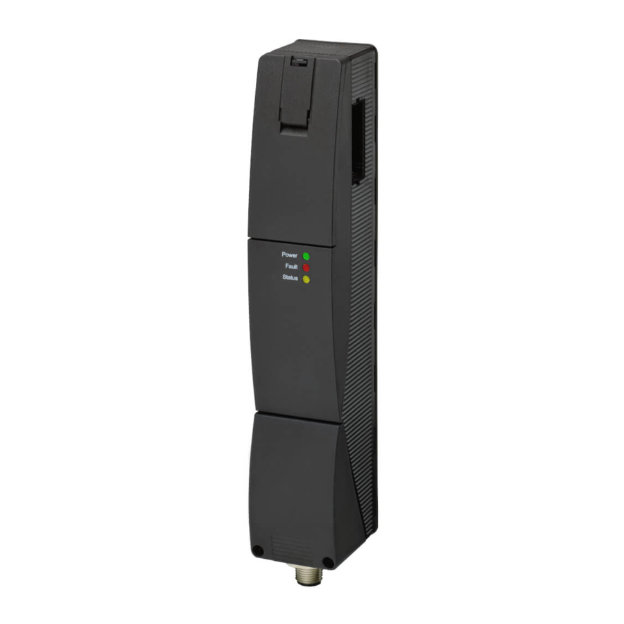
Mounting of the safety door switch and the actuator Refer to the D41G actuator's Quick Installation Manual for the corresponding actuator. The actuator must be permanently fitted to the guard doors and protected against displacement by suitable measures (tamper-proof screws, gluing, drilling of the screw heads). - Page 17 D41G Dimensions (Unit: mm) Switches D41G-@@D@-T1 Terminal block type D41G-@@D@-N2 20±1 Power Fault Status Connector type M20x1.5 A: Manual release Conduit outlet M12 B: Active RFID area...
- Page 18 47.5 +0.5 36.5 -2.5 * The D41G-A2@ (without -E1@) does not come with an inside handle. * The above shows the model for a left door. The locking part position of the D41G-A2R (-E1@) for a right door is reversed.
- Page 19 D41G-A1@-E0 For light door Example of mounting actuator D41G-@@@@-@@+D41G-A1@ For light door 46.5 5 1.5 ± * The above shows the model for a light door. The locking part position of the D41G-A1R (-E0) for a right door is reversed.
- Page 20 (125 kHz): 100 mm. D41G-A2 Admissible mounting set-up Representation of installation options Actuators D41G-A2 is available for exterior installation. The safety door switch D41G is placed outside the hazardous area. Right door Switch With emergency exit...
-
Page 21: Mounting Method
• Distance between safety door switch and actuator unit or D41G) emergency exit: 7.5 +0.5/-2.5 mm • Screws M6 (not included in delivery with safety door switch D41G) • Torque: 8 N·m • Wall thickness of actuator: 8 mm (see step 11) •... - Page 22 The emergency exit handle must be in upright position when closed. For left door 10.Insert sliding blocks as shown (included in delivery with D41G-A2) To be observed: For right door Observe the alignment (notch) of the sliding blocks •...
- Page 23 D41G D41G-A1 The actuator D41G-A1 is mounted with a return spring. The spring travel is maximum 5 mm. The distance between the flange of the actuator and the switch enclosure must be 5 ± 1.5 mm with the actuator inserted.
-
Page 24: Troubleshooting
24 V *1 24 V safety door switch locked Flashes *2 Error 0 V (24 V) 24 V (0 V) Additionally for variant D41G-1/-2: Teach-in procedure actuator Flashes started Only D41G-2: Tampering Flashes protection time *3 *1. After 30 min: disabling due to fault *2. -
Page 25: Safety Precautions
D41G Safety Precautions Be sure to read the precautions for all models in the website at: http://www.ia.omron.com/. Indication and Meaning for Safe Use Warning Indications WARNING Indicates a potentially hazardous Use only appropriate components or devices situation which, if not avoided, will... - Page 26 7. Tighten the screws with a specified torque. 33.Do not wire the product to an input of a safety controller in parallel. 8. Use the wires specified by OMRON to wire the product. (Refer to 34.Disconnect the product and the controller connected to the product Connection on page 10.)
-
Page 27: Set-Up And Maintenance
D41G Set-up and Maintenance/Disassembly and Disposal Set-up and Maintenance Functional testing The safety function of the safety components must be tested. The following conditions must be previously checked and met: 1. Fitting of the Switch and the actuator 2. Check the integrity of the cable entry and connections 3. - Page 28 MEMO...
-
Page 29: Terms And Conditions Agreement
Return of any Products by Buyer must be approved in writing by Omron before shipment. Omron Companies shall not be liable for the suitability or unsuitability or the results from the use of Products in combination with any electrical or electronic components, circuits, system assemblies or any other materials or substances or environments. - Page 30 For the most recent information on models that have been certified for ISO 13849-1 (PLe) * The actuator is sold separately. safety standards, refer to your OMRON website. Refer to Safety Precautions on page 17 For the most recent information on models that have been certified for...
Need help?
Do you have a question about the D41G and is the answer not in the manual?
Questions and answers