Table of Contents
Advertisement
Quick Links
Quick Start Guide
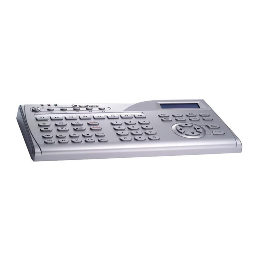
GV-Keyboard V3
Thank you for purchasing GV-Keyboard. This guide is designed to assist the new
user in getting immediate results from the GV-Keyboard. For advanced
information on how to use the GV-Keyboard, please refer to GV-Keyboard V3
2016/4/29
User's Manual on the Software CD.
English
© 2016 GeoVision Inc. All rights reserved.
KBV3-QG-D
Advertisement
Table of Contents

Related Manuals for GeoVision GV-Keyboard V3

Summary of Contents for GeoVision GV-Keyboard V3
- Page 1 Thank you for purchasing GV-Keyboard. This guide is designed to assist the new user in getting immediate results from the GV-Keyboard. For advanced information on how to use the GV-Keyboard, please refer to GV-Keyboard V3 2016/4/29 User’s Manual on the Software CD.
- Page 2 Every effort has been made to ensure that the information in this manual is accurate. GeoVision, Inc. makes no expressed or implied warranty of any kind and assumes no responsibility for errors or omissions. No liability is assumed for incidental or consequential damages arising from the use of the information or products contained herein.
-
Page 3: Table Of Contents
Contents Contents..........................i 1. Introduction ........................1 Packing List......................1 System Requirements ..................... 1 2. Options..........................2 3. Rear Panel Overview ...................... 3 4. Hardware Installation ..................... 4 Connecting to One GV-System / GV-VMS / GV-Control Center ......4 Connecting to Multiple GV-System / GV-VMS / GV-Control Center......5 Connecting Multiple Keyboards for Different Monitors .......... -
Page 4: Introduction
1. The GV-Keyboard V3 for GV-System / GV-VMS / GV-Control Center has a different button design. 2. The GV-Keyboard V3 is protected with a password. When you use the Keyboard for the first time, you will need to enter the default password ”0000” to unlock it. -
Page 5: Options
2. Options Optional devices can expand the GV-Keyboard V3’s capabilities and versatility. Contact your dealer for more information. Device Description GV-Joystick GV-Joystick facilitates the PTZ camera control. It can be either plugged into the GV-System / GV-VMS for independent use or connected to GV-Keyboard V3 to empower the operation. -
Page 6: Rear Panel Overview
3. Rear Panel Overview Name Function Joystick Connects to GV-Joystick for PTZ control. DC 12V Connects to the power adaptor. USB1 Port Connects to one GV-System / GV-VMS / GV-Control Center. RS-485 Port (RJ-11) Through the supplied Wall Terminal Block, the RS-485 port can connect to: •... -
Page 7: Hardware Installation
4. Hardware Installation When connecting the Keyboard, please note: 1. You can only connect the Keyboard using either USB port or RS-485 port on the Keyboard. 2. To use RS-485 connection, the 485 communication has distance limitation of 600 meters (1968.5 feet). -
Page 8: Connecting To Multiple Gv-System / Gv-Vms / Gv-Control Center
4.2 Connecting to Multiple GV-System / GV-VMS / GV- Control Center To use the Keyboard to control up to 36 GV-System / GV-VMS / GV-Control Center, build the connection through the Keyboard’s RS-485 port. Item required for connection: • Supplied RJ-11 Cable •... - Page 9 The diagram below illustrates the wiring to multiple GV-System / GV-VMS / GV-Control Center and uses GV-NET Card as RS-485/RS232 interface converter as example.
-
Page 10: Connecting Multiple Keyboards For Different Monitors
4.3 Connecting Multiple Keyboards for Different Monitors To use multiple Keyboards to control assigned monitors, you need to use RS-485 cables to connect additional Keyboards to RS-485 / RS-232 interface converters, and then connect these RS-485 / RS-232 interface converters to the GV-System / GV-VMS / GV-Control Center through USB ports. -
Page 11: Installing Usb Drivers
New Hardware Wizard pops up, ignore the Wizard and follow the steps below to install the driver: 1. Insert the Software CD. This window pops up. 2. Select Install Geovision USB Devices Driver. This dialog box appears. 3. Click Install to install the driver. When the installation is complete, this message will appear: Install done! 4. -
Page 12: Running The Keyboard Controller
6. Running the Keyboard Controller To control the Keyboard, you need to run the mcamctrl.exe program always at the background. 1. Run mcamctrl.exe from the GV folder / GV-Control Center folder. Note: For GV-VMS, you can also start the program from Windows Start menu, selecting GV-VMS folder and select Keyboard &... - Page 13 4. Click ► to start the service. The Keyboard is now enabled to control GV-System / GV- VMS / GV-Control Center. For details on the Keyboard & Joystick Controller dialog box, see Running the Keyboard Controller in GV-Keyboard V3 User's Manual. Note: To use the Keyboard to control multiple GV-Systems / GV-VMS / GV-Control Centers, see 6.2 Setting a Keyboard for Multiple GV-Systems / GV-VMS /...
-
Page 14: Setting Function Keys
6.1 Setting Function Keys You can set up hot keys for instant access to many functions. 1. Click a function key (F1-F8) to be configured. If multiple Keyboards are connected, first select one from drop-down list. [GV-System] [GV-VMS] [GV-Control Center]... -
Page 15: Setting A Keyboard For Multiple Gv-System / Gv-Vms / Gv-Control Centers
To print the function key labels, see GV-Keyboard V3 User’s Manual. 6.2 Setting a Keyboard for Multiple GV-System / GV-VMS /... -
Page 16: Assigning Keyboards For Different Monitors
Note: Be sure to verify the driver installation of each Keyboard in the Ports field of Windows Device Manager. If the driver of any Keyboard is not installed properly, select Install or Remove GeoVision GV-Series Driver on the Software CD to re-install it. - Page 17 3. Assign a Keyboard to a specific monitor. Use the Monopoly Mode. • For GV-System, click the Setting button of Monopoly Mode. • For GV-VMS, Monopoly Mode is not available. Instead, go to GV-VMS main screen, click Toolbar , select Accessories, and select GV-KB and GV- Joystick Configuration, you can see the dialog box like figure 1-16.
- Page 18 [GV-System] [GV-VMS] [GV-Control Center] 4. Click each Device tab to define every Keyboard. 5. You can also set up hot keys for instant access to many functions. See 6-1 Setting Function Keys section above. 6. Click ► to start the service. Every Keyboard is now enabled to control the designated monitor.
-
Page 19: Connecting Ptz Cameras
7. Connecting PTZ Cameras You can connect up to 32 PTZ cameras to the GV-Keyboard V3 directly for PTZ control. For the supported PTZ protocols and brands, see Supported PTZ Protocols and Brands, Appendix, GV-Keyboard V3 User’s Manual on the software CD. -
Page 20: Installing Ptz Cameras
7.1 Installing PTZ Cameras The PTZ cameras can be connected to the Keyboard through RS485 or RS422 wiring. Items required for connection: • Supplied RJ-11 Cable • Supplied Wall Terminal Block • Supplied Power Adaptor Note: Because RS-485 communication has distance limitation, the distance between the Keyboard and PTZ cameras must be within 600 meters (1968.5 feet). -
Page 21: Setting Up Ptz Cameras
Alternatively, you can press P2, enter a two-digit number and press OK to select a PTZ camera. For details, see Direct Connection to PTZ Cameras, Chapter 3, GV-Keyboard V3 User’s Manual on the software CD. -
Page 22: Overview
8. Overview GV-System / GV-VMS GV-Control Center... - Page 23 Section A ☼ Yellow POWER LED. Red RX LED (Receive). Green TX LED (Transmit). Changes GV-System / GV-VMS server ID. Select a PTZ camera to control. Configures the Keyboard parameters, including password, key beep and auto-lock period. Sets up the PTZ camera settings. Displays the firmware version.
- Page 24 GV-Control Center: Switches Matrix Views in GV-Control Center. Turns full screen view on/off. Starts/Stops recording. Turns the sound on/off on single view. Switches ViewLog players. For this function, you must have opened and connected to 5 ViewLog players. Switches the screen divisions. Force all output devices in Advanced I/O List of I/O Central Panel to be triggered.
- Page 25 Increases playback speed. Speed + Decreases playback speed. Speed - Switches to the previous screen or camera. Switches to the next screen or camera. Numeric Enters the login password; Selects a specific camera; Changes the buttons Time Setting in ViewLog. Section C Zooms in the display image of PTZ camera in GV-System / GV-VMS;...
-
Page 26: Upgrading The Firmware
9. Upgrading the Firmware GeoVision will periodically release the updated firmware on the website. The new firmware can be simply loaded into the Keyboard by following the steps below. Note: The firmware upgrade is only supported by GV-Keyboard V3. Warning: While the firmware is being updated, the USB cable must not be removed.
Need help?
Do you have a question about the GV-Keyboard V3 and is the answer not in the manual?
Questions and answers