Table of Contents
Advertisement
Advertisement
Table of Contents

Related Manuals for Lab599 Discovery TX-500


Summary of Contents for Lab599 Discovery TX-500
- Page 1 HF/50MHz Transceiver TX-500 USER MANUAL v03.2021...
- Page 2 LEGEND Warning Important Note This content is subject to change. Download the latest version from https://lab599.com/downloads/ If you have any questions about this document, please contact Lab599 by sending a message to support@lab599.com. Copyright © 2020 Lab555 All Rights Reserved.
-
Page 3: Table Of Contents
Table of Contents Introduction ........................... Controls end user interface .................... Device body and controls ....................User Interface ......................... Protections ........................... Basic Operations ....................... Getting Started ......................Using the Menu ......................Band Selection ......................Mode Selection ......................VFOs A and B ........................ - Page 4 Table of Contents 02. CW Pitch ......................... 03. CW Speed ........................ 04. CW Weight ......................05. CW Key ........................06. AGC ......................... 07. RF ..........................08. Power ........................09. GAIN ........................10. NR Level ........................11. NB Level ........................12. SQL ..........................
-
Page 5: Introduction
Introduction On behalf of our development team, we want to thank you for choosing the TX-500 Discovery. The TX-500 is an ultra compact all-mode transceiver ideal for travelling. Its compact size and weight mean that you can take the instrument to remarkable places, where radio work will give you an unforgettable experience. -
Page 6: Controls End User Interface
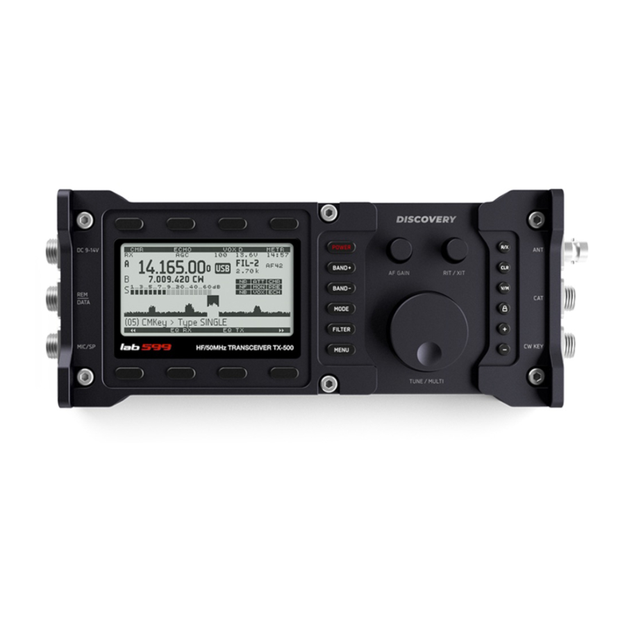
Controls end User Interface DEVICE BODY AND CONTROLS Front view Tune VFO A, B / Menu Settings Receiver gain control (RX mode) RX / TX offset Top function keys Monitor volume (TX mode) Bottom function keys Power On/Off RIT/XIT On / Off Clear RIT / XIT Band Up / Down VFO / Memory... - Page 7 Controls end User Interface Left side DC 9-15V MIC/SP Power supply Microphone / Speaker DATA 1 – SPEAKER – * 2 – MIC IN 1 – GND 3 – PTT IN 2 – DC IN (9-15V/3A max) 4 – SPEAKER + 5 –...
-
Page 8: User Interface
Controls end User Interface USER INTERFACE Main display — Function buttons — Information bar title Step VFO (Step RIT/XIT), Hz Clock TX/RX mode or LOCK VFO battery low Clock Hight temperature Autogain control Supply voltage alert (delay 1-10) VFO offset, Hz (RIT/XIT) - Page 9 Controls end User Interface — VFO A / B — Info block 1 VFO A Filter band width Receiver gain (0-100) Monitor (0-100) Basic VFO Radio frequency gain Volume (-50+5) VFO B Basic modes or alternative modes: A B C D E F G —...
-
Page 10: Protections
Protections OVERVOLTAGE PROTECTION When exceeding 15.0 volts, the transceiver won’t allow switching to TX mode, (the voltage indicator on the display will become inverse) a significant excess (more than 16 volts) it can cause the protective fuse to burn out, as well as the failure of the transceiver! Use a power source or battery with a voltage of 9 to 15 volts and a current of at least 3 Amps. - Page 11 Protections HIGH SWR PROTECTION If the impedance of the antenna is different than 50 ohms and there is no antenna tuner connected, the SWR indicator on the display will show a value greater than 1.0. If the SWR value is 3.0 or more (the SWR indicator on the display will be inverse), the transceiver will automatically reduce the power output.
-
Page 12: Basic Operations
Basic Operations GETTING STARTED Before using the TX-500, you’ll need to connect a power supply, speaker-microphone and an antenna, at minimum. Left side Right side Power supply Connect antenna Speaker-microphone Unfold Leg AF GAIN — Controls receiver AF gain (volume). USING THE MENU The menu is used to tailor the transceiver to your operating preferences. -
Page 13: Mode Selection
Basic Operations MODE SELECTION Each mode is described briefly below. Later sections cover each mode in detail. Tap D one or more times to select USB (LSB), CW (CWR), DIG, AM or FM mode. Long push selects alternate modes, such as CW reverse (CWR). Also, long push returns normal mode. •... -
Page 14: Rit
Basic Operations Incremental Tuning, or receive incremental tuning, provides a means of adjusting the receive frequency without affecting your transmit frequency. This control is sometimes called a clarifier since it can be used to tune in SSB voice signals. But RIT can also be used in all modes, in the event that a station calls you slightly off-frequency. - Page 15 Basic Operations • Adjust mic gain level: Push and select MIC, rotating MTUNE/MULTI. METR VOX L VOX D METR TX Metr Menu Up Menu Down SubMenu While speaking into the mic, adjust F>09 > Gain > MIC (mic gain). While speaking, adjust mic gain for maximum 5-7 bars on a scale. Mic gain for the TX-500 mic is typically 3-7.
-
Page 16: Receive Settings
Basic Operations RECEIVE SETTINGS • RF gain is normally left at (-0). Reducing RF gain may be useful in some strong-signal conditions. • SQL: Squelch is used to mute the receiver until a signal appears. The control adjusts the signal threshold required for squelch to “open,” unmuting the receiver. •... - Page 17 Basic Operations EXAMPLE (RX) SSB FILTER ADJUSTMENT: (CHANGE FIL-3) Set FIL-3: Bandwidth: 2.4 kHz; Passband: 600Hz to 3kHz 1. Long-Push E to enter filter RX SBB FIL-1 LF 600 adjustment menu. The parameter to Menu Up Menu Down NumFil be adjusted is shown in the bottom line of the display.
-
Page 18: Advanced Operating
Advanced Operating FREQUENCY MEMORIES V/M (VFO/Memories) — The TX-500 has 100 general-purpose frequency memories (00-99), Each memory stores VFO frequency, modes, and other settings. To store a general-purpose memory (00-99): Push I, then locate the desired memory by rotating the MTUNE/MULTI knob. The VFO frequencies presently stored in each memory will be shown as you scroll through them. -
Page 19: Receive Audio Equalization (Rx Eq)
Advanced Operating To use split, first tap N> to set VFO B to the same mode, frequency, and filter set- A->B tings as VFO A. Then tune VFO B up about 2 kHz. Finally, tap N> (the icon will turn on). VFO B is now controlling your transmit frequency. This is where the switch comes in: it reverses the A and B VFOs so that you’re tempo- A<>B... -
Page 20: External Power Amplifier Control
Advanced Operating EXTERNAL POWER AMPLIFIER CONTROL To control the PTT function of the power amplifier, you must connect pin 2 (PTT OUT), open collector, of the REM / DATA connector to the PTT control relay of the external power amplifier (usually this is the "PTT"... -
Page 21: Voice Message Memory
Advanced Operating VOICE MESSAGE MEMORY For recording and later playback of the short voice messages, the TX-500 provides 2 memory slots with a duration of 20 seconds each. To record, you need to press and hold one of the "VXM" keys 1, 2 for more than 1 one sec- ond. -
Page 22: Accessories
Accessories HAND SPEAKER-MIC Hand speaker-mic, The hand speaker-mic was designed specifically for the TX-500. It includes a high-quality mic element, speaker, rugged plug, PTT switch and external speaker plug. POWER CABLE The power cable for external power source DC 9-15V with 3A FUSE. FUSE MICROPHONE AND HEADPHONE ADAPTER WITH PTT With this adapter, you can connect a regular headset or microphone and headphones. - Page 23 The TX-500 can interface to most common types of computers via included CAT cable. It has an FT232 and PL2303 chipset. For adapter with PL2303 chipset uses driver, that can be downloaded from www.lab599.com. For the adapter with the FT232 chipset, additional installation of drivers is not required. *...
-
Page 24: Firmware Upgrades
Visit the Discovery TX-500 software download page (lab599.com/downloads/) to download the latest versions of the required drivers, software and the transceiver firmware upgrades. CHECKING YOUR FIRMWARE VERSION After switching on your Discovery TX-500, the firmware version will appear briefly at the bottom of the screen. Firmware ver 1.00.00 DOWNLOAD THE SOFTWARE AND FIRMWARE 1. -
Page 25: Remote Control
Remote Control COMPUTER CONTROL AND LOGGING With appropriate software, any computer with an RS232 or USB port can be used to control the TX-500. Use CAT-USB cable (see page “Accesories”). Third-party logging and contesting software is available for various computers and operating systems. Select KENWOOD as the target radio. -
Page 26: Menu Functions
Menu Functions 00. Valcoder VFO Encoder Mode Selector The valcoder specifies the mode of the VFO encoder. Select with MTUNE/MULTI. • Plain: The speed of change in frequency when turning the MTUNE/MULTI knob is linear. The step is determined by the setting of K L on the front panel, and is also mode-de- pendant. -
Page 27: Agc
Menu Functions • Rev: Disable or Enable. When Enabled, the dit and dah side of the paddle are reserved.Side of the paddle are reversed. Preferred by left-handed Ops. Default: Type = single; Auto = Iambic A; Rev = Disable. 06. AGC Defines the AGC Time Constant (slow-fast) •... -
Page 28: Nb Level
Menu Functions 11. NB Level Noise Blanker • Adjustable from 40 to 100 with MTUNE/MULTI. The Noise Blanker is a DSP feature used for reducing certain types of pulsed noise (i.e., lightning or automotive ignition noise). Default: 50 Adjust for best noise reduction. 12. -
Page 29: 17. Save Band Vfo
Menu Functions 17. Save Band VFO Band change occurs only VFO A (VFO A) or together with VFO B (VFO A&B). Defaults: VFO A 18. EQL RX / TX • Select RX or TX using Submenu • Select Band (Low Freq. / Mid Freq. / High Freq.) with Adjust Equalization Level with MTUNE/MULTI: from 1 to 100;... -
Page 30: Type Tone
Menu Functions 24. Type Tone Defines type of signal transmitted during TONE Mode. Choose tone type with MTUNE/MULTI. • Normal = one tone (1000 Hz) for tuning antenna matchbox or amplifier; • Dual = two tones (1000Hz and 2000Hz) for testing SSB IMD. Defaults: Normal. -
Page 31: Maintenance
Maintenance CLOCK BATTERY REPLACEMENT Required tools and parts 1. Hex key 1.5 mm; 2. Hex key 3 mm; 3. Battery CR 2032. Remove the RF and RIT/XIT knobs. Using the hex key (1.5 mm), unscrew the TUNE/MENU knob. With hex (3mm), unscrew the bolts indicated in the scheme. - Page 32 Maintenance Remove the top cover. Since the top cover is mounted on internal connectors, it is remove with effort. Replace the battery (CR 2032). Reassemble the transceiver in reverse order.
-
Page 33: Specifications
Specifications GENERAL FEATURES • 160-6-meter ham bands; • General ‘receive’ coverage 0.5 - 56.0 MHz; • All modes: SSB, CW, DIG, AM, FM; • High-performance 32-bit floating-point DSP; • Current drain as low as 100 mA in ‘receive’ mode (backlight on, preamp off, no signal); •... - Page 34 Specifications OTHER FEATURES • Internal CW keyer with 10-300 СPM range; • 100 general-purpose memories store VFOs, modes, etc.; • Computer control via USB; • Full remote-control command set (with kenwood emulates); • One-click online firmware upgrades (with free PC software). PACKAGE INCLUDE 1.
-
Page 35: Fcc Information
WARNING: MODIFICATION OF THIS DEVICE TO RECEIVE CELLULAR RADIOTELE- PHONE SERVICE SIGNALS IS PROHIBITED UNDER FCC RULES AND FEDERAL LAW. CAUTION: Changes or modifications to this device, not expressly approved by Lab599 Inc., could void your authority to operate this device under FCC regulations. Amateur Radio Operation Only... - Page 36 Lab599 inc. Russia, Altai region, Rubtsovsk city support@lab599.com www.lab599.com...
Need help?
Do you have a question about the Discovery TX-500 and is the answer not in the manual?
Questions and answers