
Summary of Contents for American Eagle Goals PRO Series
- Page 1 October 4, 2017 PRO SERIES Installation Instructions - FM54, FM60, FM72 American Eagle Goals - Customer Service Phone: 1-844-422-4625 Email: sales@aegoals.com 2017 AEGoals Pro Series Front Mounted Actuator...
-
Page 2: Safety Instructions
• Installation and assembly of this product will require bending, heavy lifting/carrying and that can lead to injury. Exercise caution during assembly. Use caution when using this system 2017 AEGoals Pro Series Front Mounted Actuator... - Page 3 Item Description 1st-NUT Pro Series 9” x 9” bolt pattern template TEMPLETE L-Bolt - (4) required NOTE: 3/4” Nut - (12) required ALLOW 3" OF THREAD 3/4”...
- Page 4 (#2) L-Bolts above the (#1) template to prevent NOTE: them from being lost. ALLOW 3" OF THREAD ABOVE 1st NUT LOCATED BELOW TEMPLETE AS SHOWN Diagram 2 2017 AEGoals Pro Series Front Mounted Actuator...
- Page 5 Step 4. Note: Wet concrete has the potential to setup very quickly depending on several conditions. These conditions include but are not limited to: • Air temperature, humidity and the exposure to direct sunlight. 2017 AEGoals Pro Series Front Mounted Actuator...
- Page 6 *Experienced Installer Tip: A great deal of success has been had using the spray adhesive as an anti-seize lubricant during the assembly process. Simply apply the spray adhesive to the bolt threads before threading on the nut and tighten with hand tools as you normally would. 2017 AEGoals Pro Series Front Mounted Actuator...
- Page 7 (#6) nylon tube adhering them to the sides of the Y-arm. This will help prevent them from falling off when raising the Y-arm into position. DETAIL#12 LOWER ARM Diagram 4 TO POLE 2017 AEGoals Pro Series Front Mounted Actuator...
- Page 8 Dirty threads will cause the stainless hardware to lock up or seize. Once a nut and bolt seizes, it must be cut apart and replaced. Diagram 5 2017 AEGoals Pro Series Front Mounted Actuator...
- Page 9 *Experienced Installer Tip: When attaching the jack to the jack adapter brackets it helps to keep the hardware a little loose in order to properly line up the bolt holes. Once everything is lined up and in place proceed with tightening the hardware. Diagram 6 2017 AEGoals Pro Series Front Mounted Actuator...
- Page 10 ABS washers and slide them over the (#19) gray nylon tube adhering them to the sides of the Y- arm bracket. This will help prevent them from falling off during assembly. DETAIL# 11 CONNECTING JACK TO LOWER ARM Diagram 7 NOTE: PLASTIC WASHERS ARE TO BE PLACED IN BETWEEN. 2017 AEGoals Pro Series Front Mounted Actuator...
- Page 11 • Secure the base of the pole to the anchor bolts using the four (#4) washers and four (#3) nuts. • Tighten the four (#3) nuts snug, but do not fully tighten them at this time. Diagram 8 2017 AEGoals Pro Series Front Mounted Actuator...
-
Page 12: Step 7 - Backboard Attachment
Diagram 9. This is a pivot point. Do not over tighten these bolts. Note: View of backboard upper & lower arms from above. Upper and lower arms attach to the inside of the backboard mounting tabs. Diagram 9 2017 AEGoals Pro Series Front Mounted Actuator... - Page 13 The four (#3) nuts located below the baseplate of the pole can be adjusted to fine tune the backboard. Once you are satisfied, double check to make sure the four (#3) nuts are tight. This area intentionally left blank. 2017 AEGoals Pro Series Front Mounted Actuator...
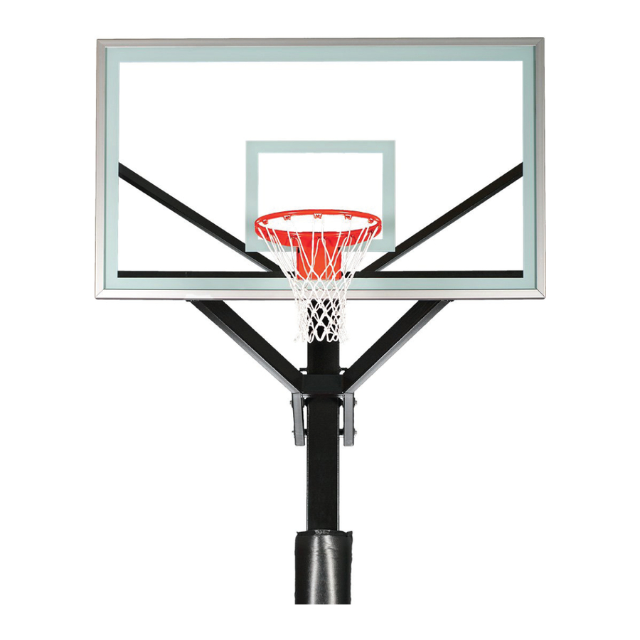
- Page 14 • Place a level across the rim side-to-side and adjust the rim until it is level. • Finish tightening all four (#21) nuts. RIM IS NOT SHOWN FOR CLARITY THE RUBBER OCTAGON IS TO BE PLACED IN BETWEEN THE RIM AND GLASS AS SHOWN. Diagram 10 2017 AEGoals Pro Series Front Mounted Actuator...
- Page 15 • A cordless drill is recommended for installing the (#5) rim screws. • Do not over tighten the (#5) screws as they could strip. • Attach the net to the rim. Diagram 11 2017 AEGoals Pro Series Front Mounted Actuator...
-
Page 16: Step 11 - Height Indicator Attachment
While this is a rare occurrence, it is possible depending on the height of your anchor system in relationship to the slope of the driveway where the rim height measurement was taken. Diagram 12 LOWER JACK STICKER 2017 AEGoals Pro Series Front Mounted Actuator... -
Page 17: Care And Maintenance
• The goal should not be adjusted above or below the heights indicated on the height adjustment decal. All adjustments should be made under adult supervision. Questions? Phone: 1-844-422-4625 Email: sales@aegoals.com www.aegoals.com 2017 AEGoals Pro Series Front Mounted Actuator... - Page 18 October 4, 2017 Hardware Identification Sheet 2017 AEGoals Pro Series Front Mounted Actuator...
- Page 19 October 4, 2017 Hardware List - Pro Series FM Key # Description Quantity Anchor Kit 3/4 - 10 Hex Nut 3/4” Flat Washer Basketball Goal 1/2” - 13 x 1” SS HHCS 1/2” - 13 x 2” SS HHCS 1/2”-13 x 3 1/2” SS HHCS 1/2”-13 x 4 1/2”...
-
Page 20: Warranty
Legal Remedies: This warranty gives you specific legal rights and you may also have other rights which may vary from state to state. 2017 AEGoals Pro Series Front Mounted Actuator... - Page 21 No part of this manual may be reproduced in any form or by any means electronic or mechanical, including photocopying, recording or by any information storage and retrieval systems without the express written consent of American Eagle Basketball Systems. 2017 AEGoals Pro Series Front Mounted Actuator...
Need help?
Do you have a question about the PRO Series and is the answer not in the manual?
Questions and answers