Table of Contents
Advertisement
Advertisement
Table of Contents

Related Manuals for BRG Precision Products DuraTime RC100

Summary of Contents for BRG Precision Products DuraTime RC100
- Page 1 Wireless Clock System Technical Guide BRG Precision Products 600 N. River Derby, Kansas 67037 http://www.DuraTimeClocks.com sales@brgproducts.com 316-788-2000 Fax: (316) 788-7080 (Patents Pending) Updated: 8/7/2020 Our mission is to offer innovative technology solutions and exceptional service.
-
Page 2: Table Of Contents
Table of Contents OVERVIEW ................................3 DURATIME FEATURES AND OPTIONS ......................6 PLANNING .................................. 9 INSTALLATION................................. 9 OPERATION ................................17 ALARM CONFIGURATION ..........................21 ALARM CONFIGURATION WORKSHEET ....................... 25 MASTER CLOCK CONFIGURATION MENU ....................30 ETHERNET COMMUNICATIONS ............ERROR! BOOKMARK NOT DEFINED. COMMUNICATIONS PROTOCOL ........................ -
Page 3: Overview
Overview The DuraTime wireless clock system is specifically designed for applications where precision and reliability are of great importance. In most cases, external time updates are not required. The RC100 includes an oven controlled oscillator with an accuracy of one second in 20 years (2 Parts per Billion). - Page 4 DuraTime Multi-path Wireless Communications The examples listed on these pages are simplified for communicating system concepts. The number of actual clocks in a system could easily number in the thousands, either densely located, or spread over a wide area, with complete coordination of all communications. Signal Paths of an Active Network Installing Battery powered Analog Cocks When the wireless clock network is active, all clocks are within range of one or...
- Page 5 Alarm/Tone Generator with a Partially Active Network Wireless GPS Time Receiver Multiple wireless alarm/tone generators may be deployed. Each alarm/tone The RC160 wireless GPS receiver will provide time updates to one or more generator must be located with 150 feet of a continuously active component of the master clocks.
-
Page 6: Duratime Features And Options
This clock system will perform flawlessly for any size facility, or campus. Master Clock Package Contents DuraTime RC100 Master Clock AC Power Adapter with plugs for North America, UK type, Europe and Australia 10 feet (15M) of Cat-5 network cable... - Page 7 General Specifications: DuraTime Radios Frequency 2405 to 2480 MHz Protocol 802.15.4, Proprietary Mesh Network Operating Mode Modulation Direct Sequence, Spread Spectrum, Digital Data Speed 250 Kbps Operating Voltage 2.1 to 3.3 Volts Output Power +20 dBm Rx Sensitivity -97 dBm Range 3,000 + feet (900 meters) Operating Temperature...
- Page 8 RC100 Master Clock Environment: -32 degrees F to 120 degrees F, Humidity: 0% to 95% non-condensing Internal Time Battery Backup: 10 year NiMH rechargeable battery – uses one millionth of a watt in standby mode Clock Accuracy: The RC100 incorporates an ultra-high precision oven controlled quartz oscillator (OCXO) that is accurate to 2 parts per billion, or about one second in 20 years without NTP.
-
Page 9: Planning
Planning All DuraTime wireless devices receive and re-transmit time data to other devices. This includes master clocks, analog clocks, digital clocks, alarm interfaces, repeaters and sensors. This method of repeating data allows coverage of any size of facility or campus. The rule-of-thumb for the placement of wireless devices is to locate them no further than 150 feet (45m) apart for areas with many wall partitions, such as offices, dormitories and hospitals. - Page 10 An optional GPS receiver is available for the master clock. This receiver sends the time received from the GPS satellites wirelessly to the master clock. The GPS receiver can be used in addition to NTP time for a redundant time source. Configuring the Time Zone Offset If the time displayed is incorrect after the synchronization indicator appears, then time zone rules may require reconfiguration.
- Page 11 Alarm relay connections along with RS422 connections. The DuraTime RC100 master clock includes connections for power, alarm relay and Ethernet. The alarm relay includes 10 Amp contacts. Larger loads should make use of a slaved relay. There are two primary network types: Periodically Active and Continuously Active.
- Page 12 recommended to plug the wall repeater into an outlet located high on the wall to prevent accidental damage or tampering. Dropped ceiling repeaters are also available. Be sure to secure the wall repeater to the electrical outlet using the RC140 Wall Repeater screw hole provided in the repeater housing.
- Page 13 The RC150 Mini-Master is a high precision synchronized master clock, incorporating a temperature compensated quartz oscillator, multi-path radio transceiver and a 10 year battery to maintain the internal time. Mini-Master Clock Operation Press the yellow On/Off button to power on the unit. The LED will flash twice per second. This indicates the unit is in repeater only mode.
- Page 14 To change the channel of the mini-master clock, press the On/Off button to power the unit on. Then simultaneously press the Repeater Only and Transmit Time buttons, then release. The indicator light will flicker momentarily and then go out. Next, press the Transmit Time button equal to the desired channel number.
- Page 15 The wireless relay / tone generator includes a configuration dip switch. Switch position 1 sets the audio output, up=high (1 volt P-P), down=low (0.5 volt P-P). Switch position 2 sets the device function (up=audio player w/ relay following, down=timed relay). Switch positions 3-6 sets the alarm zone number (binary 1-12).
- Page 16 = 12 = 13 9 10 = 10 = 14 9 10 9 10 = 11 = 15 9 10 The relay output of the master clock is always a timed or steady state, and does not follow any audio play, or zones. An internal speaker is available when the device is in audio player mode.
-
Page 17: Operation
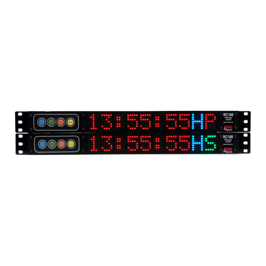
Operation The DuraTime master clock obtains time updates from local or public time servers, and/or from the optional GPS receiver. The time received is used to update the master clock’s internal temperature compensated quartz oscillator. The internal clock is backed up using a 10 year Lithium battery to prevent time disruptions due to power outages. - Page 18 configured for single master clock operation. It will always transmit in this configuration, regardless of the presence of other master clocks or sync reception. By default, the LED display will cycle through several screens to display different information. Momentarily pressing the blue TC button will display various other formats. Six digit time Eight digit date This screen indicates whether the clock is a primary or secondary master clock...
- Page 19 time and includes indicators for sync source and primary or secondary status. A “T” will display on the primary clock that is actively transmitting. Another available display format includes four digit time following by status indicators. A “T” will display on the primary clock that is actively transmitting. When a slave clock receives a time update, it immediately repeats the signal to all other clocks within range.
- Page 20 be some time later. If a battery clock is in low power mode, removing and reinserting the batteries, pressing the receive button, or shorting the reset pins will not enable for reception. A mini-master will not help. In this case the clock must moved to a location in direct range of the master clock.
-
Page 21: Alarm Configuration
Alarm Configuration Each master clock has 999 total alarm settings that can be configured to activate a wireless audio alert / relay device at various times and days. For example a start lunch break alert horn could sound a constant tone for three seconds beginning at 12:00 noon, Monday through Friday. - Page 22 Enter the description of the alarm item into the box next to the Create New Alarm Record button. Be sure to press the Enter key after entering the description to confirm the entry. Next, select the day-of-the-week for the alarm to activate. Then select the time of day. Be sure to select AM or PM. Now click on the Alarm Function drop down box to view the available alarm options.
- Page 23 Each wireless alarm receiver may be configured to one of twelve zones, with zone 1 the default. The alarm schedule program may be used to select any combination of the twelve zones. For example, zone 1 could be used for one area of a building and zone 2 for another area.
- Page 24 When the Active Alarm Schedule number is set to 0, a date range may be used to automatically switch from one alarm schedule to another. Select a date range to use (1-20) and the alarm schedule number to activate. Then enter the desired date range.
-
Page 25: Alarm Configuration Worksheet
Alarm Configuration Worksheet Alarm Alarm Alarm Alarm Day Alarm Alarm Sound Type or Relay Alarm Position Hours and Seconds Code Zone Duration Schedule 1-99 Minutes Number Number... - Page 26 Clock Supervision Monitor The Clock Supervision/Monitor feature is used to interrogate clocks to determine if they are receiving and storing time updates. Only LED digital clocks are supported at this time. It does not report malfunctions with the visual display. The monitor program will test the communications link between the control PC, and between the master and between the Master clock and the slave clocks.
- Page 27 The Supervision/Monitor screen includes a variety of features as described below. The database window lists the clock address, location description, master clock time/date, slave clock time/date and supervision status. The location description should indicate the location of the clock The Master Time indicates the time/date of the master clock at the time the slave clock was tested. The Slave Time indicates the time/date stored and maintained by the slave clock.
- Page 28 Clicking on the Start Monitor button starts the monitoring process. The green Monitoring Enabled message will be displayed on the screen. During monitor, if a clock does not respond, or the master clock does not respond, or a clock responds with the incorrect time, an message will be displayed indicating a problem.
- Page 29 The next screen shows two messages that will generate an alert message, even though the third clock is correct. An alert message will also be displayed if the slave clock time is not close to the master clock time. The monitor program must remain running while the slave clocks are monitored. The monitor program must also remain running if Auto Start Monitor is selected.
-
Page 30: Master Clock Configuration Menu
Master Clock Configuration Menu General Menu Navigation: Clock/Timer/Counter configuration is accomplished by editing parameters using a simple menu system. Only four buttons are used to navigate the menu. The Mode button enters the Menu. The Up and Down buttons move up and down through the menu items, and are used to change parameter values. - Page 31 6= Sends a test alarm command to wireless audio players to play audio file 1 on zone 1. Pressing the Mode and Up buttons at the same time will restore user defaults. If user defaults are unavailable, factory defaults will be restored. First Menu Second Value...
- Page 32 First Menu Second Value Mode Description and Instructions Level Menu Range Mode Number Level displaying real time. 0,10 Daylight Saving Time This mode selects the rules to use when automatically switching between Daylight and Standard time. 0=disable daylight time; 10=rule based switching (default) See also Mode 52 and Mode 45-20, Mode 45-21 1-99 00:00...
- Page 33 First Menu Second Value Mode Description and Instructions Level Menu Range Mode Number Level 5=Friday, 6=Saturday, 7=Sunday, 8=Everyday, 9=Weekdays, 10=Sat/Sun, 11=Mon/Wed/Fri, 12=Tue/Thu, 13=Tue-Sat., 14=Mon-Thu, 15=Mon-Sat Display and time source number 1 is used for alarm activation in multi-display clocks. In addition to day-of-the-week combination codes, Mode 29 also accepts any day combination.
- Page 34 First Menu Second Value Mode Description and Instructions Level Menu Range Mode Number Level this method to operate. Scheduled Alarm Time Activation 0=deactivate scheduled alarms, 1=activate scheduled alarms (default). 0-99 Clock Address for PC Control (default=0) If the address value sent equals the value specified in this mode, then the clock will accept the data packet.
- Page 35 First Menu Second Value Mode Description and Instructions Level Menu Range Mode Number Level 0 = (default) Single master clock operation - send time packets even if other master clocks are also sending time packets. The master clock will continue transmitting even if the sync source is lost.
- Page 36 First Menu Second Value Mode Description and Instructions Level Menu Range Mode Number Level 2=calibrate the TCXO using the OCXO or RbO once per hour, 3=calibrate the TCXO using the OCXO or RbO once per day Port 65 - OCX Reset Output Port 66 - OCX 1 BPS input 0-199 Automatic Leap Second Adjustment...
- Page 37 First Menu Second Value Mode Description and Instructions Level Menu Range Mode Number Level date range. There are 20 date ranges available. The Mode 38 function has changed. It now determines which schedule is active for date ranges defined in Modes 53, 54, 55 and 56.
- Page 38 First Menu Second Value Mode Description and Instructions Level Menu Range Mode Number Level 0=Disabled (default) 1=Enabled The mode reconfigures the RC100 as a Time Zone Master clock for analog wall clocks. 0-99 Control Button Lockout and Addressable Clock Function 0=Disabled (default) To lockout all buttons, set 32-4=0...
- Page 39 First Menu Second Value Mode Description and Instructions Level Menu Range Mode Number Level show real time, while the third displays may be a timer with external control that requires active Up and Down buttons. The remote could be used to access any of the displays.
- Page 40 First Menu Second Value Mode Description and Instructions Level Menu Range Mode Number Level 4= activate full time reception every day. If Mode 37-62=7 or 9 then everyday, no transmissions will occur if the hour is less than 2 or greater than 19. This mode can be used for externally powered clocks and DuraTime battery powered analog clocks.
- Page 41 First Menu Second Value Mode Description and Instructions Level Menu Range Mode Number Level 1-18 8=default This mode determines the number of time zones in an analog time zone display. Mode 18 should be set to the same value. 9-23 RC60 Analog Clock Movement Second Motor Hour to turn Off 20=turn off motor at 20:00 (default) This mode determines the hour to turn the analog clock movement second motor off.
- Page 42 First Menu Second Value Mode Description and Instructions Level Menu Range Mode Number Level system when Mode 37- 80=2. This setting is only intended for Chouchin (RC50) movements. If Mode 37-80 is set to 0 to disable the power saving mode, the movement will return to normal operation the next time it receives a time update.
- Page 43 First Menu Second Value Mode Description and Instructions Level Menu Range Mode Number Level 7=Sunday. For example, 357 = the last Sunday in March, or 1117 = the First Sunday in November. If the value >2000 then the right two digits represent the day of the month. The left two digits, minus 20, equal the month.
- Page 44 First Menu Second Value Mode Description and Instructions Level Menu Range Mode Number Level This special diagnostic mode is for factory use only. This mode is used to reset the software without removing power from the display. Restore-User Default Configuration This mode may be used to retrieve the custom configuration from memory if it was previously stored using mode 50-6.
- Page 45 First Menu Second Value Mode Description and Instructions Level Menu Range Mode Number Level then group is 1 the default. This feature reduces the number of alarm entries required in some schedule situations. Mode 27 set the hours and minutes. Mode 29 sets the day of the week (required).
- Page 46 First Menu Second Value Mode Description and Instructions Level Menu Range Mode Number Level receives on all channels. Mode 75-6=n - 1= reboots the radio , 2=restore initialization defaults...
-
Page 47: Ethernet Communications
Ethernet Communications Overview Once the clock is connected to the network and power is applied, DHCP is used to automatically assign each clock an IP address on the network. The clock will then search the Internet or local area network for NTP time servers. NTP (Network Time Protocol) is a uniform method of sending time over a computer network. - Page 48 User Name and Password The menu in the left column allows selecting several sections of the interface. A user name and password is required to enter any section other than the main page. The default user name is: user The default password is: password The user name and password should be changed after installation.
- Page 49 Clock Name - is the user defined name used to identify the device during a network search. SNTP Sample Interval - is the time in minutes between SNTP time updates. The default is one minute. SNTP Extra random delay – if this box is checked, a random delay will be added to the sample period so that all clocks to not attempt to access the time server at the same time.
- Page 50 Analog clock Ethernet configuration. DO NOT USE WITH DIGITAL CLOCKS DO NOT USE WITH DIGITAL CLOCKS The network interface provide UTC time to digital clocks. Time displays rules are configured in each digital clock. For analog clocks, time displays rules are configured in the Ethernet interface.
- Page 51 Network Configuration Enable DHCP – check to enable automatic IP address configuration using DHCP. Uncheck to use manual address configuration. The address fields will be grayed out when checked. IP v4 Address – enter the IP address using version 4 protocol Subnet Mask –...
- Page 52 Clocks purchased after April, 2019 To display the clock’s IP and MAC address on the clock, using either the buttons or remote control, press and hold mode button. The display will blink for a few seconds and then begin counting up. When the count reaches 9, release the button. The IP and MAC addresses will display.
- Page 53 Change the password as needed. Be sure to store in a safe location for future reference. Click on the Apply button to invoke the change. Upload Firmware The factory may provide a file to update the firmware in the Ethernet interface. The Update Firmware screen facilitates the update process.
- Page 54 Your network firewall must allow the clock to access the Internet through port 123. The clock must have the default NTP time server IP address loaded into the NIC. If using named SNTP servers, be sure a valid DNS address is provided, or use only ...
-
Page 55: Communications Protocol
Communications Protocol The time, date and data string is 35 bytes long, beginning at position 0 begin data string - position 0, length 1: "*" position 1, length 2: seconds position 3, length 2: minutes position 5, length 2: hours position 7, length 2: day position 9, length 2: month position 11, length 4: four digit year... -
Page 56: Wireless Gps And Ethernet Gps Time Receivers
Wireless GPS and Ethernet GPS Time Receivers The GPS satellites obtain their time from the U.S. Atomic time standard, providing legally traceable time to the wireless clock system. Two GPS models are available. The RC161 receives GPS time and sends it wirelessly to all master clocks within radio range. The MCR100GPS receives GPS time and sends it over the computer network to any number of master clocks. - Page 57 GPS antenna is water tight and may be mounted outdoors, on a roof or exterior wall. The following diagrams illustrate antenna positioning: View of S ky Sate llite Sate llite Inside Satellite Sate llite View of S ky Inside GPS antenna Window Ante nna GPS a ntenna...
-
Page 58: Warranty Agreement
Product specifications; c) repairs have been done to it other than by BRG Precision Products, Inc. or its authorized service centers, or as assigned by BRG Precision Products;... - Page 59 6. Claim Limits Claims are limited to repair or replacement, or if in BRG Precision Products, Inc.'s discretion that is not possible to reimbursement up to the purchase price paid for the Product. In no event will BRG Precision Products, Inc.'s liability under this Agreement exceed the purchase price paid for the Product.
- Page 60 90 days. -------------------------------------------------------------------------------- Pricing: BRG Precision Products reserves the right to change prices without prior notification. Prices do not include taxes and BRG reserves the right to arrange for insurance on all orders. --------------------------------------------------------------------------------...
- Page 61 These copies must include the BRG Precision Products, Inc.
- Page 62 Limited Warranty BRG Precision Products, Inc. warrants that the processors or memory use to store the software is free from physical defects in material and workmanship under normal use for a period of sixty days from the date of purchase.
-
Page 63: Index
Index Agreement ............58, 59 Defaults, Restore-Mode 50-1 ........43 Alarm Display Active alarm schedule-Mode 37-1 ......36 12/24 hour format– Mode 23 ........31 Master/Slave Operation– Mode 32-16 ..... 33 Brightness, auto– Mode 32-14 ......... 33 Panic alarm button-Mode 37-2 ........ 36 Intensity, auto–...
Need help?
Do you have a question about the DuraTime RC100 and is the answer not in the manual?
Questions and answers