
Summary of Contents for Amit RRE-F/001
- Page 1 RRE-F/001 Remote I/O unit with Ethernet interface Operation manual Version 1.03 rre-f001_g_en_103...
- Page 2 RRE-F/001 AMiT, spol. s r.o. does not provide any warranty concerning the contents of this publication and reserves the right to change the documentation without any obligation to inform about it. This document can be copied and redistributed under following conditions: 1.
-
Page 3: Table Of Contents
RRE-F/001 Contents History of revisions ..................4 Related documentation ................... 4 Introduction ..................5 Technical parameters ................6 2.1. Dimensions ..................... 8 2.2. Recommended drawing symbol ..............9 Labelling ..................... 10 3.1. Type label ..................... 11 Conformity assessment ..............12 4.1. -
Page 4: History Of Revisions
RRE-F/001 History of revisions Document name: rre-f001_g_en_103.pdf Revision Date Author Changes 11. 3. 2014 Šach Jaroslav New document 16. 2. 2016 Šach Jaroslav Digital Inputs schematic change, plastics weight correction, adding chapters Labelling, Packaging 27.10.2016 Šach Jaroslav Peak current correction 25.4.2017 Šach Jaroslav DI voltage values correction. -
Page 5: Introduction
RRE-F/001 1. Introduction RRE-F/001 is a remote I/O unit with Ethernet interface. ▪ 8 × digital input / output Basic features ▪ 1 × Ethernet, connector M12 ▪ PoE power supply according to IEEE 802.3af ▪ Mounting on base plate ▪... -
Page 6: Technical Parameters
RRE-F/001 2. Technical parameters Processor STM32F207VET6 Internal FLASH memory 512 KB 128 KB EEPROM 2 KB 8 × Digital inputs/ Number of inputs / outputs 1 × 8 outputs Configuration 8 × LED Input / output state indication Common pole... - Page 7 RRE-F/001 Mechanics Mechanical design Formed metal 1.5 mm – cover Color type Powder color – cover Colour Light grey / RAL 7035 On panel, 2 × M5 bolt with cylindrical head Mounting Ingress protection rate IP30 – netto 0.76 kg ±5 % Weight –...
-
Page 8: Dimensions
RRE-F/001 2.1. Dimensions Fig. 1 - RRE-F/001 dimensions in mm rre-f001_g_en_103 8/29... -
Page 9: Recommended Drawing Symbol
RRE-F/001 2.2. Recommended drawing symbol Following drawing symbol is recommended for RRE-F/001 unit. Only part of it can be visible in following examples. RRE-F/001 GNDIO VDDIO IO01 IO02 IO03 IO04 IO05 IO06 IO07 IO08 Fig. 2 - Recommended drawing symbol for RRE-F/001... -
Page 10: Labelling
RRE-F/001 3. Labelling There is a type label on the top side of the RRE-F/001. Image below shows the label position. RRE-F/001 TYPE xxxxxxxx xx-xx-xx-xx-xx-xx APP x.xx / LDR x.xx 802.3af, Class 0 WEIGHT 0.76 kg TEST OK-MU HiPot HiPot-OK DATE 02.02.2016... -
Page 11: Type Label
RRE-F/001 3.1. Type label Fig. 4 - Type label example Description Content Note AMiT logo Manufacturer logo QR code Manufacturer’s QR code TYPE RRE-F/001 Type name xxxxxxx Serial number xx-xx-xx-xx-xx-xx X2 MAC address APP x.xx / LDR x.xx Firmware version 802.3af, Class 0... -
Page 12: Conformity Assessment
RRE-F/001 4. Conformity assessment The equipment meets the claims of Czech government decree NV616/2006; the conformity assessment has been performed in accordance with harmonized standard EN 50121-3-2:2006. Tested in accordance Type of test Classificati with standard EN 55011:2009 Industrial, scientific and medical Complies equipment –... -
Page 13: Other Tests
RRE-F/001 4.1. Other tests This product was assessed and approved for use in railway applications according to standards: Tested in accordance Type of test Classification with standard Railway applications – Electromagnetic EN 50121-3-2:2006 Complies compatibility – Part 3-2: Rolling stock –... -
Page 14: Power Supply
RRE-F/001 5. Power supply RRE-F/001 unit is powered via data lines of Ethernet network line according to PoE standard. In the case of need for overall output current exceeding 80 mA it is possible to connect external power supply. See the chapter 7.3 for more information. -
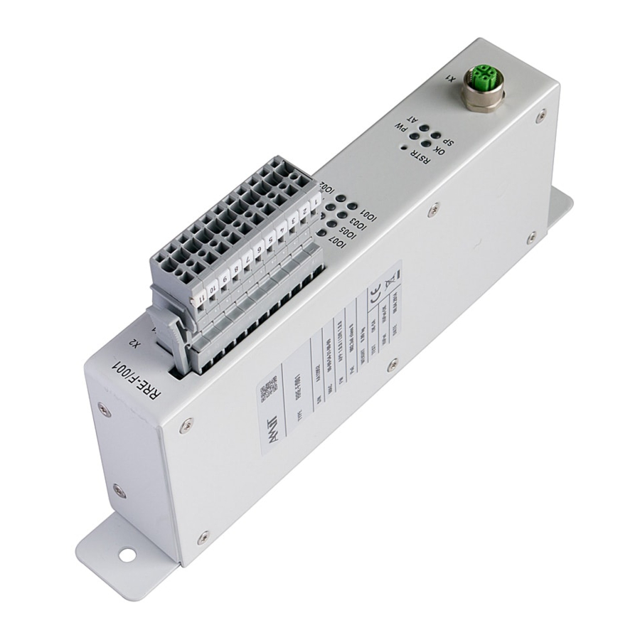
Page 15: Elements Of The Front Panel
RRE-F/001 6. Elements of the front panel Fig. 6 - Elements of RRE-F/001 front panel Elements of Subject User element title front panel Inputs / outputs connector. Input / output state indication The RESTORE button Unit status LED indication Ethernet line state LED indication... -
Page 16: Inputs/Outputs
RRE-F/001 7. Inputs/outputs Unit RRE-F/001 provides 8 digital inputs / outputs. All inputs / outputs can be used as single inputs, or like outputs with reverse reading. X2 connector Connector Signal Type of signal on RRE-F/001 wiring Unit chassis GNDIO... -
Page 17: Digital Outputs
Logical 0 for Input/output that is intended for using only in input mode (end switch off), so that the real pin level is not affected. 7.2. Digital outputs Outputs of RRE-F/001 unit are realized via MOS switches. All outputs are protected against short circuit and reverse polarity. 7.3. Power supplying of digital outputs Unit output circuits are powered from the VDDIO terminal. -
Page 18: Input / Output State Indication
RRE-F/001 7.4. Input / output state indication The status of single inputs / outputs is indicated by LEDs marked as IO01 – IO08. Depending on user configuration, the LEDs can show either real state or required state of inputs / outputs. Configuration is done via Ethernet interface. -
Page 19: Ethernet
RRE-F/001 8. Ethernet The X1 connector used for Ethernet interface connection is located on the unit’s front side. LEDs indicating link state are located above the Ethernet connector. Fig. 11 - Location of Ethernet connector and indication LEDs Ethernet line... -
Page 20: System Leds
RRE-F/001 9. System LEDs State of unit is indicated by 2 LEDs on front panel. Fig. 13 - Location of system LEDs Unit status Colour Status Meaning indication Green Does not light Power supply is not connected to unit Lights... -
Page 21: Configuration
RRE-F/001 10. Configuration All RRE-F/001 unit’s configuration can be done over Ethernet interface. Some changes in settings will take effect after unit’s restart. Unit is fitted with RSTR button to restore factory settings. The button must be pressed while switching the unit power supply on. The OK LED which is located right next to the connector X1 shortly blinks after successful execution of factory settings. -
Page 22: Mounting
RRE-F/001 11. Mounting 11.1. Mounting instructions RRE-F/001 unit is intended for mounting on the panel. 11.2. Mounting holes Unit can be mounted into any position. Unit is mounted by two M5 bolts. Fig. 15 - Mounting of RRE-F/001 unit rre-f001_g_en_103... -
Page 23: Installation Rules
PE terminal of power supply connector must be connected with local installation earthing terminal. All PE connections must be realized with as low as possible impedance. Technical parameters of the unit RRE-F/001 are guaranteed only, when the equipment is connected according to manufacturer recommendation. 23/29... -
Page 24: Factory Settings
RRE-F/001 12. Factory settings Factory Parameter Default value setting IP address 192.168.1.1 Network mask 255.255.255.0 Default gateway 0.0.0.0 rre-f001_g_en_103 24/29... -
Page 25: Ordering Information And Completion
13. Ordering information and completion Unit RRE-F/001 Complete, see chapter 13.1 Completion of remote I/O 13.1. Completion RRE-F/001 Part Quantity RRE-F/001 unit Connector counterpart WAGO 769-111/021-000 Routine testing protocol Insulation testing protocol Certificate of product quality and completeness 25/29 rre-f001_g_en_103... - Page 26 Box label contains information as follows: Description Content TYPE RRE-F/001 NETTO 0.76 kg BRUTTO 0.89 kg 1 pc Serial number – AMiT logo – QR code – CE mark TYPE NETTO BRUTTO ABCD Fig. 16 - Mounting of RRE-F/001 unit rre-f001_g_en_103 26/29...
- Page 27 RRE-F/001 15. Storage To prevent any damage to the device please keep the following rules. Packed unit The unit in the original box must be stored only under environmental conditions defined in technical parameters. The device must be kept away from water, oil or any other liquid which can damage the packing.
-
Page 28: Maintenance
The equipment can be then cleaned disassembly by dry soft brush or vacuum cleaner, only when turned-off and disassembled. Note: To avoid any damage to the electronics during the cleaning with disassembly please contact the AMIT technical support. rre-f001_g_en_103 28/29... -
Page 29: Waste Disposal
RRE-F/001 17. Waste disposal Electronics The disposal of electronic equipment is subject to the regulations on handling disposal electrical waste. The equipment must not be disposed off in common public waste. It must be delivered to places specified for that purpose and recycled.
Need help?
Do you have a question about the RRE-F/001 and is the answer not in the manual?
Questions and answers