Advertisement
Quick Links
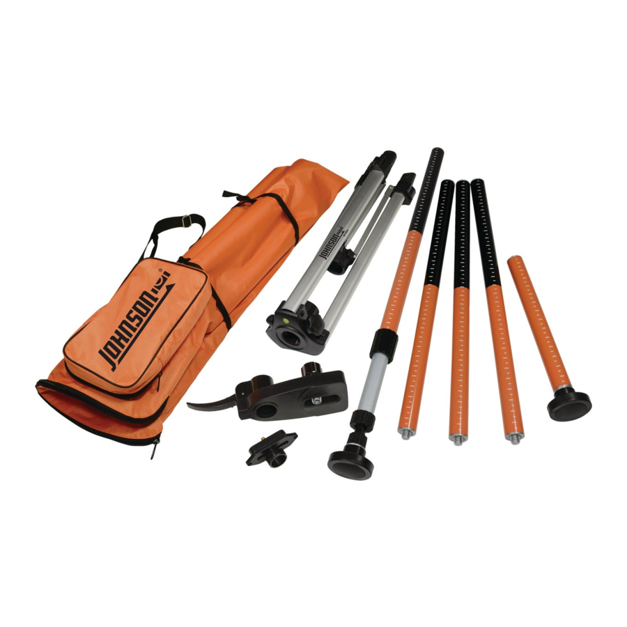
40-6301 Laser Mounting Pole
with Tripod Assembly Instructions
Thank you for purchasing this 40-6301 Laser
Mounting Pole with Tripod.
KIT CONTENTS:
5 Telescoping Poles
3 Center Poles
1 Spring Loaded Floor Pole
1 Ceiling Pole
Tripod
Laser Mounting Platform
1/4" - 20 Adapter
Carrying Case
1/4" - 20 ADAPTER
ASSEMBLY INSTRUCTIONS FOR
NON-FLOOR TO CEILING APPLICATION
1. Locate tripod and unlock the black plastic clamp on the leg (A) to
extend to your desired height (B). Lock the clamp to keep leg in this
fixed position. Repeat for the other the two legs.
A
2. Locate spring loaded floor pole and insert through tripod center
holes from the bottom (C). If pole doesn't slide through top hole,
then loosen tripod locking screw by turning counterclockwise (D).
Do not remove locking screw. Position tripod in upright position with
spring loaded end on the floor (E).
C
TRIPOD
CARRYING CASE
LASER MOUNTING PLATFORM
B
D
E
TRIPOD
LOCKING
SCREW
3. Use leveling vial to level tripod and make
adjustment to each leg as needed (F).
SPRING LOADED
FLOOR POLE
TELESCOPING
CENTER
4. IF 1/4" - 20 adapter is not required, skip to #5. To use included 1/4"-20
POLES (3)
adapter for laser or optical instrument (G), use 3/16" Phillips head
screwdriver. Unscrew both screws on bottom (H) and remove 5/8"-11
CEILING
adapter (I). Install 1/4"-20 adapter (J), use same screws and install
POLE
onto bottom of adapter (K).
G
5. Locate laser mounting platform (L). Unlock the quick release lock by
moving lock to an upward position and hold in the highest upward
position. Attach laser mounting platform to threaded end of center
pole column (M). To lock onto pole, push lock downward (N). Assemble
remaining center pole or poles together as needed for jobsite height
requirement (O) and attach to assembled center pole in tripod.
L
LASER
QUICK
MOUNTING
RELEASE
SCREW
LOCK
6. Unlock and slide laser mounting platform to desired
position on pole for laser or optical instrument. Lock into
position by pushing quick release downward.
7. For greatest stability, extend legs to the farthest position.
Fully lock tripod locking screw (P). Assembly is complete (Q).
P
LEVELING VIAL
H
I
J
M
N
TRIPOD
LOCKING
SCREW
Download this manual at
www.johnsonlevel.com/manuals
40-6301
F
K
O
Q
Advertisement

Summary of Contents for Johnson 40-6301
- Page 1 40-6301 Laser Mounting Pole with Tripod Assembly Instructions 3. Use leveling vial to level tripod and make adjustment to each leg as needed (F). Thank you for purchasing this 40-6301 Laser Mounting Pole with Tripod. LEVELING VIAL KIT CONTENTS: TRIPOD...
- Page 2 40-6301 Laser Mounting Pole with Tripod Assembly Instructions 5. You can extend the overall height of the laser pole by twisting the black connector piece on the end of the spring loaded pole (V). Rotate the black ASSEMBLY INSTRUCTIONS FOR connector piece 1/8"...
Need help?
Do you have a question about the 40-6301 and is the answer not in the manual?
Questions and answers