Table of Contents
Advertisement
Quick Links
Advertisement
Table of Contents

Summary of Contents for Flymaster M1
- Page 1 M1 USER MANUAL Document version:1.3...
- Page 2 All rights reserved. Except as expressly provided herein, no part of this manual may be reproduced, copied, transmitted, disseminated, downloaded or stored in any storage medium, for any purpose without the express prior written consent of FLYMASTER Avionics Lda. herein FLYMASTER avionics. FLYMASTER Avionics hereby grants permission to download a copy...
-
Page 3: Table Of Contents
2.2 M1 Keys ......... 2.3 Switching M1 On and Off ....... - Page 4 7.4.3 Tank Empty ........7.4.4 Average Fuel Consumption ......7.4.5 Set Sensor .
-
Page 5: Introduction
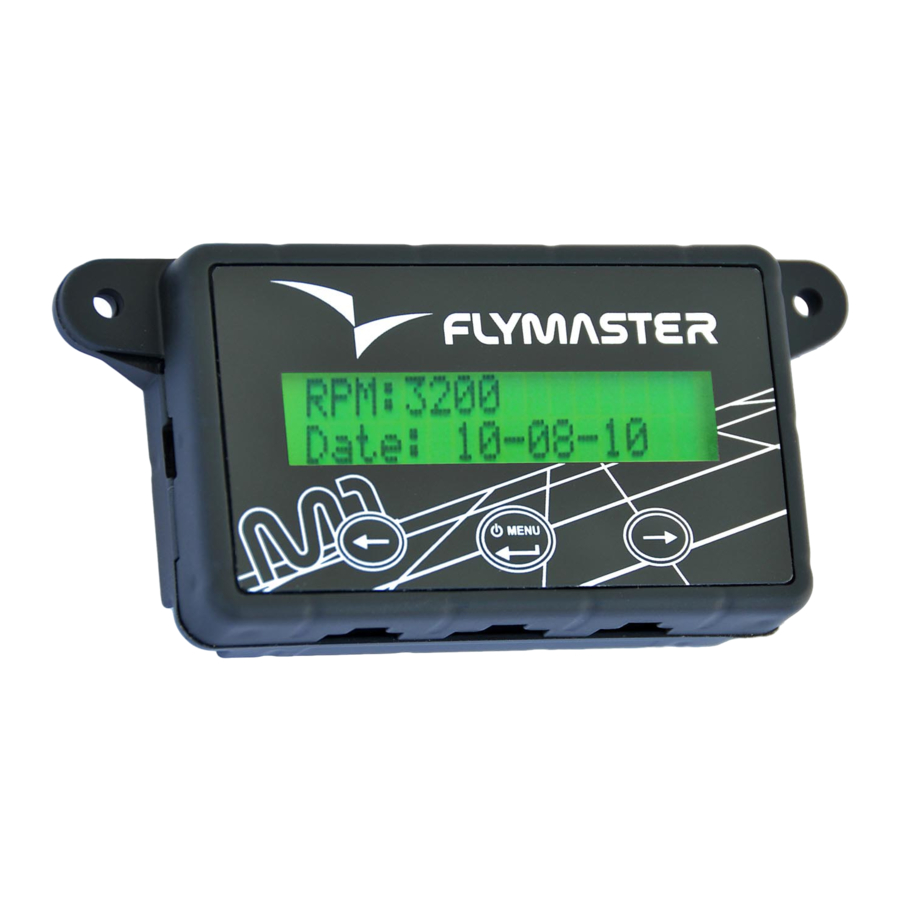
Fully charge battery before using FLYMASTER M1 for the first time. The battery may be charged by either connecting the M1 USB connector to the wall socket charger or USB cable. M1 connector can be found on the left side of the M1 (see Figure 1). -
Page 6: M1 Keys
Switching M1 On and Off To switch on the M1, briefly push the S2 key. This will display the start up screen showing the M1 serial number, firmware version and a 10 second countdown. Pushing S3 before the end of... -
Page 7: Flight Data
M1. To switch off the M1 , activate menu mode by pushing the S2 (menu) key. Using keys S3, or S4, chose “Shutdown” menu option. Finally, push the S2 3. Flight Data (Enter) Key to confirm. -
Page 8: Settings
(see section 7.3). 4. Settings Settings menu allows the configuration of several M1 parameters. To access the different items on the Settings menu you can use the LEFT(S1) and RIGHT(S3) keys. Pushing the ENTER (S2) enter the selected function. -
Page 9: Units Settings
Exit Main Menu Returns to Main screen Units Settings The "Units Settings" menu option allows the user to change the M1 interface units. In this Settings the user can change the Temperature Sensor , and the Fuel Units. -
Page 10: Tank Calibration
4.4.2 Sensor Calibration The fuel sensor supplied with M1 is factory calibrated. However, the sensor length can be cut to size . Cutting the fuel sensor length involves several tasks being the last one the Sensor Calibration. This menu option allows fuel sensor calibration after being cut. The calibration procedure is necessary in order the M1 recognize the new length. -
Page 11: Set Sensor
Set Sensor The M1 automatic detects if a fuel sensor is connected, but if the user is using the M1 without the fuel sensor, or want to turn it off in the current flight, in the "Set Sensor" option the user can set the Sensor Off... -
Page 12: Fuel Sensor Position
Figure 5: Fuel Sensor Installation Example Fuel Sensor Position Considering the height measured by the sensor is proportional to the length of the immersed part, the fuel sensor should be vertically installed (see Figure 6 a)). However, an inclined position is possible provided that sealing is guaranteed (see Figure 6 b)). - Page 13 Fuel Sensor .Cutting Procedure The fuel sensor supplied with M1 has a default length. If required the sensor can be shortened. The first step for shortening the fuel sensor is to decide the correct length of the metallic tube which will be inserted in the tank.
- Page 14 Figure 8: Sensor length 5.2.2 Cutting the Metallic Tube The sensor cut should be made using an adequate tool (eg. Pipe Cutter; fine toothed hacksaw). Figure 9: Cutting the Sensor After cutting the metallic, outer, and inner tube carefully remove the remaining jagged edges using adequate tool.
- Page 15 Figure 10: Sensor after being cut The sensor has a small hole on the bottom. This hole is necessary to allow fuel entry. (see Figure 11). Figure 11: Sensor hole If cutting the sensor leads to the elimination of the hole a new one should be made using 4 mm drill.
- Page 16 5.2.3 Sensor Calibration Procedure Sensor calibration allows the M1 to recognize the new probe length after the cutting process. The calibration process should be made after install the sensor on the tank. However, it can also be made before the installation using an adequate fuel recipient. Before start the calibration process assure that you have enough fuel to totally immerse the probe.
- Page 17 3-Choose the "Calib. Sensor" option 4- The M1 ask you to confirm the sensor calibration process. By default the flashing option is "No", so you should choose "Yes" to proceed. 5- The M1 will ask you to confirm that sensor is dry (i.e. not in contact with the fuel).
-
Page 18: Tank Calibration
The calibration process is based on a simple idea. After asking for a standard measure definition, the M1 keeps asking the user to spill measures on the tank until it is full. For each added measure the corresponding height is saved. Later the fuel quantity can be calculated by interpolation. - Page 19 S1 and S3 and confirmed using S2 Key. 6- Depending on the first value measured by the sensor the M1 can ask the user to confirm if tank is really empty. In case "No" is selected the calibration process is aborted.
- Page 20 However, the chosen value should cause fuel height variations greater than 1 centimetre. The maximum number of measures is 30. Once the calibration is done M1 can calculate data as: fuel level; average fuel consumption; remaining flight time.
Need help?
Do you have a question about the M1 and is the answer not in the manual?
Questions and answers