
Subscribe to Our Youtube Channel
Summary of Contents for EPS 56VDC IPS Series
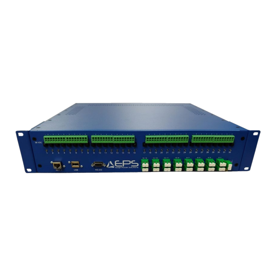
- Page 1 USER MANUAL IPS-16 IPS-32-1 & IPS-32-2 EDGE POWER SOLUTIONS 56VDC IPS SERIES USER MANUAL VERSION 4 03222021...
- Page 2 Instruction This symbol is intended to alert the user to the presence of important instructions in the literature accompanying the device. Dangerous Voltage This Symbol is intended to alert the user to the presence of un-insulated dangerous voltage within the products enclosure that may be of sufficient magnitude to constitute a risk of electric shock to persons.
-
Page 3: Table Of Contents
Table of Contents SECTION 1: • Introduction…………………………………………………………………………………………. • Quick Installation Checklist…………………………………………………………………… • Technical Support…………………………………………………………………………………. • Model IPS-32-1………………………………………………………………..………………… • Model IPS-32-2…………………………………………………………………………………. • Model IPS-16……………………….……………………………………………………………… SECTION 2: Installation • Standard Accessories…………………………………………………………………………… • Additional Required Items…………………………………………………………………… • Safety Precautions………………………………………………………………………………. • Mounting PDU…………………………………………………………………………………….. Attaching Safety Earth Ground Connection………………………………………….. •... -
Page 4: Introduction
For Product Assistance or Technical Support call: 321-499-1919 - Option 4 1.1 Quick Installation Checklist • The following steps are recommended to quickly install the EPS-RM-1x(xx)-100W-(s) Power Supply Unit for use. a) Attach Rack Mount Brackets to the Power Supply Unit b) Mount the power supply unit in rack location Connect Safety Earth Ground connection to approved ground buss d) Connect devices to output connections using properly sized wire. -
Page 5: Model Ips-32-1
(16) +56VDC Outputs (12AWG -24AWG) – (Up to 98W per output) a) SEE NOTE 1 / PAGE 1 • Optional 2x16 Passive Fiber Optic Splitter IPS-32-V1-WALL MOUNT / EPS-32-V2-WALL MOUNT • 24” W x 24” L x 6.25” • 23lbs / 26LBS •... -
Page 6: Section 2: Installation
PAGE 2 SECTION 2: Installation 2.1 Standard Accessories: IPS-32-1 • (2) 6’ C20 – 5-15P Power Cord (AC MODEL) • (1) Grounding Lug Kit • (2) Rack Mounting Ears IPS-32-2 • (1) 6’ C20 – 5-20P Power Cord (AC MODEL) •... -
Page 7: Safety Precautions
2.3 Safety Precautions: Only for installation and use in a Restricted Access Location in accordance with the following instructions. This equipment should only be installed by qualified personnel Do not block venting holes when installing this product. Allow for maximum airflow at all times above, below and each side of the unit. -
Page 8: Mounting Pdu
2.4 Attach Rack Mounting Brackets Attach mounting brackets to each side of chassis with provided screws. • • Mount PDU into a properly secured wall mount, 2 post or 4 post rack. • For wall mounting turn mounting brackets 90 degrees so that the mounting ear is flush with the bottom of the chassis. o Units should be mounted in a manner that allows for proper air intake and venting. -
Page 9: Connection Output To Field Devices
2.6 Connect Remote Device Power Cables • Observing proper polarity, connect remote device power cables. Acceptable wire sizes: 12AWG – 24AWG Choose appropriate AWG of wire based on Current, Distance & Acceptable Voltage Drop. Consult with connecting device manufacturer for device requirements ... -
Page 10: Connecting To Power Source
BLACK LEAD TO POSITIVE + INPUT Wall Mount: EPS wall mount systems may utilize locking plug system for external power connections or internal direct power supply connections from an RMS equivalent DC power source or properly configured Digital Electricity™ receiver. -
Page 11: Status Indicators & Reset Buttons
FIGURE 7.1 2.8 LED Status Indicators and Reset Buttons Each 56VDC output has a corresponding status indicator light and reset button. • Green: Indicates output ready or normal circuit condition • Red: Indicates output fault condition (Short, Over-Current or Admin Down) Push Button or Software output reset is required once fault is cleared. -
Page 12: Section 3: Optional Integrated Fiber Optic Splitter
SECTION 3: Optional Integrated Fiber Optic Splitter 3.1 Optional Integrated Splitter Connection WARNING: Avoid eye exposure to fiber optic openings on this device when connected to external equipment in any position. A fiber optic splitter is installed in this device. A connection to any position transmits invisible laser light on all ports that could be damaging to the eye.
Need help?
Do you have a question about the 56VDC IPS Series and is the answer not in the manual?
Questions and answers