Table of Contents
Advertisement
Quick Links
Advertisement
Table of Contents

Summary of Contents for Squarell Technology REMOTE
- Page 1 User manual REMOTE...
- Page 2 Version Description Date 210429 Layout changes 29-04-2021 201027 Public release 27-10-2020 Copyright © 2021 Squarell B.V., the Netherlands Under international copyright laws, neither the documentation nor the software may be copied, photocopied, reproduced, translated or reduced to any electronic medium or machine-readable form, in whole or in part, without the prior written permission of Squarell B.V., the Netherlands, except in the manner described in the software agreement.
-
Page 3: Table Of Contents
CONTENTS 1. INTRODUCTION 1.1 Glossary 2. DEVICE DISPLAY 2.1 Pinout 3. SET UP YOUR DEVICE 3.1 Device Configuration File 3.2 Special Function Device 3.3 Profile 3.4 iControl 3.5 Prepare for vehicle installation 3.6 Vehicle installation 3.7 Reset button 3.8 RS-232 protocol 4. -
Page 4: Introduction
The REMOTE is the one box solution that combines a vehicle data interface with modem functionality. The compact design houses everything you need to provide your customers with high quality vehicle data, versatile connectivity and advanced Squarell solutions. -
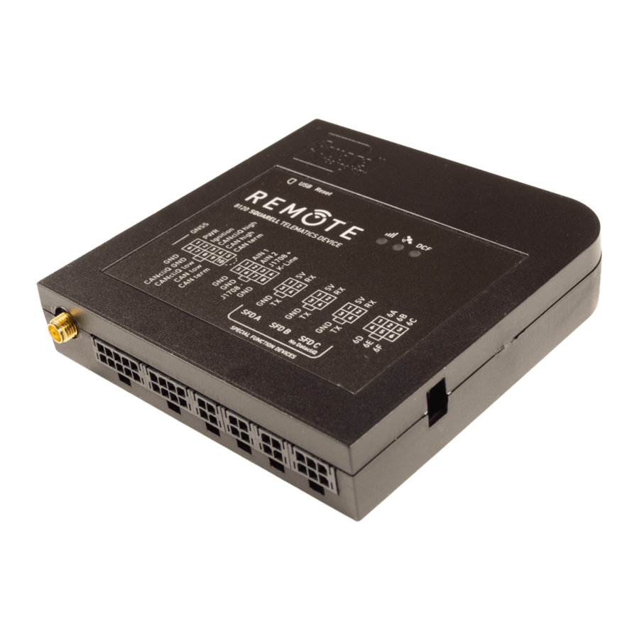
Page 5: Device Display
2. DEVICE DISPLAY Micro-SIM slot Reset button Micro-B USB slot Status LEDs Molex connector slots GNSS antenna hookup Cable tie mounting slot Cable tie mounting slot... -
Page 6: Pinout
2.1 Pinout Pin No. Name Description (Red) power supply (+10-30 V DC) Ignition (Yellow) ignition CANcliQ (Yellow) CAN high connection of the high CANcliQ CAN high (White) hard-wired CAN high connection CAN term (Blue) CAN Bus termination for the hard- wired connection (Black) ground Pin No. -
Page 7: Set Up Your Device
In paragraph 3.4 you can find the steps you need to take to get the device ready for vehicle installation. In paragraph 3.5 you can find the steps you need to take to get the REMOTE working in the vehicle. -
Page 8: Special Function Device
SFD ports are universal ports, any kind of SFD device can be connected to one of the unused SFD ports on the REMOTE. SFD port C differs from SFD port A and B: no DatacliQ can be connected to this port. -
Page 9: Icontrol
3.4 iControl To set the REMOTE, a number of messages must be sent to the device. To do this, you can use iControl. Under the "Settings" tab in the "REMOTE" section you can make various settings. If you do not use iControl but your own software, you can use the messages below to set up your device. -
Page 10: Prepare For Vehicle Installation
3.5 Prepare for vehicle installation Before installing your REMOTE device in a vehicle, there are a number of steps you need to take. Unpack the REMOTE. Insert SIM card. Make sure that Install the USB driver. Click your Nano-SIM card with PIN here to download the driver. -
Page 11: Vehicle Installation
3.6 Vehicle installation To install the REMOTE in your vehicle, follow these steps below (see the Squarell installation instruction to find the connection locations). Chapter 6 contains recommendations for installing the REMOTE. Connect the supplied cables to Connect the CANcliQ over the... -
Page 12: Reset Button
If you have a more extensive solution (tachograph connection and SFD), please follow the instructions in the drawing below. Here you can see how to connect an SFD device, the K-Line and tachograph connection. Remark: The resistance between blue and white (CAN High and CAN Low) should be 60 Ω, this should be measured without voltage on the devices. -
Page 13: Rs-232 Protocol
(e.g. fuel consumption, brake system wear, etc.). Remark: The FMS/J1939 CAN Bus output is only active if CAN Bus 1 of the REMOTE is connected to a telematics modem which reads FMS. The complete REMOTE RS-232 communication protocol can be found on our support portal (support.squarell.com)and contains all the messages that Squarell devices send and receive. -
Page 14: Led Indications
4. LED INDICATIONS 4.1 GNSS LED status GNSS has fix. GNSS is searching fix. Time 4.2 Cellular LED status SIM detected, connected to server. SIM detected, connected to provider. SIM detected, searching connection. No SIM detected Time... -
Page 15: Dcf
4.3 DCF LED status Device active. CAN Bus data is being acknowledged. Device is reading vehicle CAN Bus. Brake message received*. Device is initializing vehicle protocol and/or tachograph type. Device active. But one of the CAN Bus channels is stopped. Check CAN Bus connection and check the CAN Bus termination. -
Page 16: Characteristics
5. CHARACTERISTICS 5.1 Basic characteristics Network protocols MQTT, TCP GNSS GNSS GPS, GLONASS, BD and GALILEO Cold start sensitivity -148 dBm Accuracy (Open Sky) <2.5 m (CEP50) Hot start <1 s Cold start <35 s Cellular Technology 2G, LTE-M 2G bands GSM 850 MHz, EGSM 900 MHz, DCS 1800 MHz, PCS 1900 MHz 4G bands LTE-M... - Page 17 CAN Bus characteristics Baud rate Selectable: 10 – 1000 Kbit/sec Protocols CAN Selectable: J1939 / Layer 2 Hardware protocol CAN V 2.0a, CAN V 2.0b Default Device address RS-232 characteristics Baud rate Selectable: 300 to 230400 bps, default 115200 bps Protocols Configurable: ASCII based protocols or binary Hardware control...
-
Page 18: Mounting Recommendations
6.4 Module installation The REMOTE has two mounting slots for cable ties. By using the cable ties, the devices can be mounted at your desired location. Squarell recommends to do this at a stable point in the interior. -
Page 19: Safety Information
The REMOTE must not be disposed of with ordinary household waste. If the REMOTE is damaged or defective outside the warranty period and you choose not to have it repaired, take it to your local recycling center or dispose it... -
Page 20: Warranty
8. WARRANTY Squarell hardware products have a warranty of 24 months. For extended warranty plans, please consult a Squarell sales representative. If you face any problems with our product, please contact us using the Squarell Support Portal with full description of the problem, application environment, used DCF, serial number and model number of the device. -
Page 21: Technical Support
(support.squarell.com). Our technical department will then help you with your problem as soon as possible. If your problem has a higher priority, you can call our support department with the following phone number: +31 252 42 02 39. Squarell Technology Oude Weerlaan 27 2181 HX Hillegom The Netherlands...
Need help?
Do you have a question about the REMOTE and is the answer not in the manual?
Questions and answers