
Related Manuals for NBS-Cam MC736

Summary of Contents for NBS-Cam MC736
- Page 1 User Guide MC736 Digital LCD Color Monitor Multiple view(7”) Please read this manual thoroughly before operating the unit, and keep it for future reference. V1711.01 1.855.730.5555 www.nbs-cam.com...
-
Page 2: Table Of Contents
CONTENT 1. Precautions 2. Product 3. Monitor installation 4. Connections 5. Parts identification 6. Remote control operations 7. Menu operations 8. Specifications 9. Troubleshooting 1.855.730.5555 www.nbs-cam.com... -
Page 3: Precautions
In case of any problems, please turn off the display at once and notify our company or authorized dealer. The monitor is a complex device. Any disassembly or modification may lead to damage and void the warrantee. 1.855.730.5555 www.nbs-cam.com... - Page 4 This device complies with Part 15 of the FCC Rules. Operation is subject to the following two conditions: (1) This device may not cause harmful interference. (2) This device must accept any interference received, including interference that may cause undesired operation. 1.855.730.5555 www.nbs-cam.com...
-
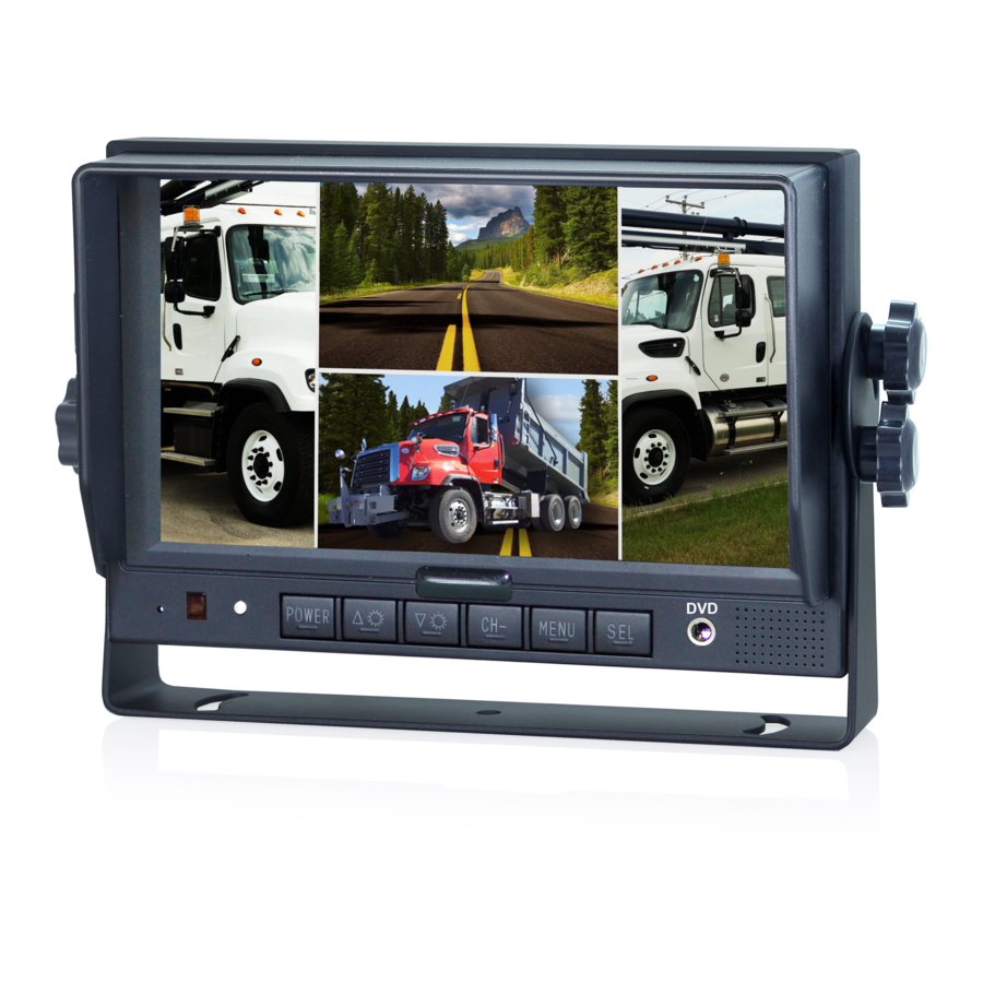
Page 5: Product
2. PRODUCT U Support Bracket Optional Center Mount Bracket AV and Power supply adapter cable IR remote control Sun shield Front panel AV input adaptor Angle adjustment screws SPECIAL NOTICE Accessories may be different for different applications. 1.855.730.5555 www.nbs-cam.com... -
Page 6: Monitor Installation
① Loosen the knob on top of the center mounting bracket in picture ④. ② Adjust monitor level by sliding the support to the desired height. ③ Adjust the angle of the monitor and tighten the knob on the center mount bracket. 1.855.730.5555 www.nbs-cam.com... -
Page 7: Connections
⑤ White: Trigger 1 ⑥ Blue: Trigger 2 ⑦ Green: Trigger 3 ⑧ Brown: Trigger 4 ⑨ Yellow: Split trigger ⑩ Black: Ground ⑪ Red: Power ⑫ DVD video input (yellow RCA) DVD Audio input (white RCA) NULL (red RCA) 1.855.730.5555 www.nbs-cam.com... -
Page 8: Parts Identification
Menu selection and display mode (single, dual, triple, quad-view, PIP image) selection ⑧ Menu control button ⑨ Jump key selector. Fast jump to the display mode specified by SYSTEM SETUP – JUMP KEY ⑩ DVD A/V input ⑪ Loudspeaker ⑫ Installation port for center mount bracket 1.855.730.5555 www.nbs-cam.com... -
Page 9: Remote Control Operations
1. Please align the remote control with the infrared-receiving window on the monitor to operate. 2. Never disassemble the remote control or allow it to drop, or become wet. 3. Press the control buttons firmly. Allow 2 seconds for the picture to change. 1.855.730.5555 www.nbs-cam.com... - Page 10 Jump key selector. Fast jump to the display mode specified by SYSTEM SETUP – JUMP KEY. ⑩ P/N: PAL / NTSC TV system selector ⑪ LANG: Press to select language of display. ⑫ REST: Press to restore factory settings. Press to go to / leave DVD channel. 1.855.730.5555 www.nbs-cam.com -10-...
-
Page 11: Menu Operations
To set the camera input(s) to be displayed when “split”trigger wire is activated. LEFT / RIGHT is to set the camera input to be displayed on the left / right side of monitor screen. AUDIO is to set the audio output from any of the four cameras. 1.855.730.5555 www.nbs-cam.com -11-... - Page 12 To set TV system: PAL / NTSC. DIMMER: To set backlighting brightness level of screen. Five levels and AUTO option are available; the higher the level, the brighter. When set as AUTO, backlighting automatically adjusts in accordance with the outer brightness. 1.855.730.5555 www.nbs-cam.com -12-...
-
Page 13: Specifications
Video Ouput 1 REC Video output - peak value: 1Vp-p, impedance: 75 ohm 1 LIVE Video output - peak value: 1Vp-p, impedance: 75 ohm Audio Output Audio Output 1 REC audio output - peak value: 1Vp-p, impedance: 4.7K ohm 1.855.730.5555 www.nbs-cam.com -13-... -
Page 14: Troubleshooting
Our products are no substitute for proper defensive driving techniques, observance of traffic laws and motor vehicle safety regulations. 1.855.730.5555 www.nbs-cam.com -14-...
Need help?
Do you have a question about the MC736 and is the answer not in the manual?
Questions and answers