
Related Manuals for Flight Systems SCU 9iS


Summary of Contents for Flight Systems SCU 9iS
- Page 1 Installation / Operation Manual SCU 9iS System Control Unit Version: 1.04 © Copyright 2021 RS Flight Systems GmbH...
-
Page 2: Table Of Contents
Preface ..............................3 System Description ...........................3 Technical Specifications ........................5 Mechanical Installation ........................7 Drawings SCU 9iS Main Unit ....................8 Drawings SCU Display Panel ....................9 Drawings SCU Front Panel ....................11 Electrical Installation ........................13 Lane A / Lane B / Lane C Connector ..................14 Auxiliary Connector ....................... -
Page 3: Preface
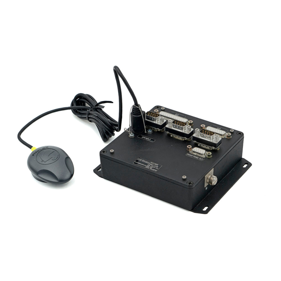
Preface Thank you for purchasing a System Control Unit from RS Flight Systems. We are pleased that you have chosen our product and are confident that it will meet all your expectations. In case of questions or problems with the unit, feel free to contact us:... - Page 4 Figure 2-1: Top view of the SCU 9iS Figure 2-2: SD Card Cover In combination with either of the two optional extension units (Front Panel including switches or Display Panel without switches), the following additional functions are offered: • Indication of the most important engine parameters, engine status and ECU faults •...
-
Page 5: Technical Specifications
Operating -20 to +70 Temperature Range -4 to +158 < 7,620 m Operating Altitude < 25,000 ft Humidity < 95 %, non-condensing Table 3-1: Technical Specification SCU 9iS Main Unit Installation / Operation Manual 16.03.2021 | V1.04 System Control Unit... - Page 6 SCU Display Panel SCU Front Panel Mechanical 90 x 66 x 23.5 mm 150 x 66 x 97.5 mm Dimensions 3.54 x 2.6 x 0.93 in 5.91 x 2.6 x 3.84 in (width, height, depth) Panel Cutout 82 x 58 mm, 12 mm corner radii 142 x 58 mm, 12 mm corner radii (width x height) 3.23 x 2.28 in, 0.47 in corner radii...
-
Page 7: Mechanical Installation
Mechanical Installation Upon delivery, undertake visual inspection of the package contents for signs of transport damage and verify the information on the type plate sticker against your order. Do not open the device housing. For longer storage of the device, select a dry and clean environment. Make sure that the device is not stored near strong heat sources and that no metal chippings or other dirt can get into the device or its connectors. -
Page 8: Drawings Scu 9Is Main Unit
Drawings SCU 9iS Main Unit Figure 4-1: SCU 9iS Main Unit (front view) Figure 4-2: SCU 9iS Main Unit (side view) 16.03.2021 | V1.04 Installation / Operation Manual System Control Unit... -
Page 9: Drawings Scu Display Panel
Figure 4-3: SCU9iS Main Unit (isometric view) Drawings SCU Display Panel Figure 4-4: SCU Display Panel (top view) Figure 4-5: SCU Display Panel (side view) Installation / Operation Manual 16.03.2021 | V1.04 System Control Unit... - Page 10 Figure 4-6: SCU Display Panel (front view) Figure 4-7: SCU Display Panel (isometric view) 16.03.2021 | V1.04 Installation / Operation Manual -10- System Control Unit...
-
Page 11: Drawings Scu Front Panel
Drawings SCU Front Panel Figure 4-8: SCU Front Panel (front view) Figure 4-9: SCU Front Panel (top view) Figure 4-10: SCU Front Panel (side view) Installation / Operation Manual 16.03.2021 | V1.04 System Control Unit -11-... - Page 12 Figure 4-11: SCU Front Panel (isometric view) 16.03.2021 | V1.04 Installation / Operation Manual -12- System Control Unit...
-
Page 13: Electrical Installation
AS27500. AWG22 (0.34 mm²) is a sufficient cross section for power supply of the SCU. Preassembled wiring harnesses are available as accessories for simplifying the installation. For part numbers see Chapter 5.7 or contact RS Flight Systems directly. Ensure that proper grounding connections are made and that the various ground potentials are not connected outside of the Main Unit. -
Page 14: Lane A / Lane B / Lane C Connector
Figure 5-1: SCU Sub-D connector pin numbering Lane A / Lane B / Lane C Connector The Lane A Connector carries the power supply pins of the SCU (Pins 1 and 5) and Display CAN Lane A (Pins 2 and 7). Table 5-3 specifies its pinout. Reverse polarity and voltage surge protection are implemented on the Lane A connector, therefore power must be supplied there. -
Page 15: Auxiliary Connector
Pin Number Signal Name Function PWR_IN do not connect CANL_B CAN Low, connect to HIC B, Pin 7 EXT_PWR_ACT do not connect EXT_DIN5 do not connect do not connect EXT_DIN3 do not connect CANH_B CAN High, connect to HIC B, Pin 8 EXT_DIN4 do not connect SPARE... - Page 16 • Pressure range: 1 to 11 bar absolute pressure • Supply voltage: 5 or 12 V • Output voltage: 0.5 VDC to 4.5 VDC Figure 5-2: Fuel Pressure Sensor Installation The standard hard- and software are designed to drive an electric MT-Propeller P-853 constant speed governor via the MOTOR+ and MOTOR- (Pins 7 and 8) outputs (function available on request).
-
Page 17: External Connector
An extinguishing diode across the relay coil is not needed and a suitable relay is available as an accessory (see Chapter 5.7). The Starter relay is intended for use on unmanned aircraft. Feel free to contact RS Flight Systems for different sensor and actuator configurations. External Connector The I/O connector offers filtered, but unregulated power output and further general I/O connections. -
Page 18: Front Panel Out Connector
Power Output (9-32 V) Table 5-7: External Connector pinout Feel free to contact RS Flight Systems for your needs regarding I/O applications. Examples are automatically controlled LANE and fuel pump switches, temperature-controlled fan activation (Intercooler, Oil cooler), UAV applications and many more. - Page 19 The pinout of the LED connector is listed in Table 5-10. For the connection of the warning lamps A and B please refer to the BRP Rotax Installation Manual 912iS / 915iS. The pre-resistors and the parallel resistors are integrated in the Front Panel and the Display Panel. Therefore, the pins 1-4 can be directly connected to the BRP Rotax HIC A and HIC B connectors.
-
Page 20: Wiring Diagram Scu
Wiring Diagram SCU Main Bus Lane A Aircraft GND Power Supply Ground HIC A CAN_LOW_1_LA CAN Low A CAN High A CAN_HIGH_1_LA Aircraft GND CAN_GND_1_LA Lane B HIC B CAN_LOW_1_LB CAN Low B CAN High B CAN_HIGH_1_LB CAN_GND_1_LB Aircraft GND Lane C Third party display... -
Page 21: Available Accessories
Available Accessories Part No. Name Description Shielded cables for the connection of the SCU Lane A, B and C to 10-135 Wiring Harness Kit SCU BRP Rotax 912/915 iS engines. Including power supply wires. Open wire ends at the side of the ECU. Length 2 m / 6.5 ft. Wiring Harness SCU Prewired shielded harness for the connection of the Front Panel or 10-148... -
Page 22: Operation
Operation Startup Power Relay Function For the Rotax 912iS / 915iS engine, the spring-loaded “Start Power Switch” (SPS), as specified in the BRP-Powertrain installation manual, has to be activated prior to engine start. As soon as START has been commanded and the engine is running, the SPS has to be released. The function of the SPS is to temporarily feed aircraft battery power to the Engine Control Unit (ECU), so that engine start is possible. - Page 23 with 0001 being the decimal number, which is incremented by one for each new file and allows for 9999 different files to be created, named and stored. The number of the last file which has been closed and written to the SD card is stored as a 4-character ASCII string in the file "TOPDAT.CFG", which is also written to the card.
- Page 24 Figure 6-4: EMDS Data Screen Figure 6-5: EMDS Fault Matrix Screen 16.03.2021 | V1.04 Installation / Operation Manual -24- System Control Unit...
- Page 25 Figure 6-6: EMDS Limits Screen Figure 6-7: EMDS generated Google Earth View Installation / Operation Manual 16.03.2021 | V1.04 System Control Unit -25-...
-
Page 26: Software Update
(“INSTALL.LOG”) is created and stored on the memory card and the update files are deleted. The standard software versions are listed in Table 6-1. Feel free to contact RS Flight Systems for customized software versions with individual SLPC algorithms. -
Page 27: Abbreviations And Terms
Abbreviations and Terms Abbreviation Description Active Aircraft Voltage Auxiliary American Wire Gauge Brightness Computer Aided Design Controller Area Network Cylinder Head Temperature CONF Configuration Coolant Temperature Direct (non-alternating) Current Do Not Connect Engine Control Unit ECU Voltage Exhaust Gas Temperature EMDS Engine Management Debriefing Station Engine Management Unit... - Page 28 RS Flight Systems GmbH Oberer Luessbach 29-31 82335 Berg | Germany +49 8178 8681 – 300 contact@rs-flightsystems.com www.rs-flightsystems.com SCU 9iS | Version: 1.04 © Copyright 2021 RS Flight Systems GmbH...
Need help?
Do you have a question about the SCU 9iS and is the answer not in the manual?
Questions and answers