
Subscribe to Our Youtube Channel
Summary of Contents for Subzero Wolf MD24
-
Page 1: Table Of Contents
800.222.7820 MD Microwave Drawers Service Manual General Information Installation Information Controls & Operation Component Access & Removal Troubleshooting Guide Wiring Diagrams... -
Page 2: General Information
General Information MD24 and MD30 MD24 and MD30 INTRODUCTION This Wolf Microwave Drawer Technical Service Manual, Part #824820, has been compiled with information provided by the Sharp Electronics Corporation. This manual provides the most recent technical service information that will enable the service technician to troubleshoot and diagnose malfunctions, perform necessary repairs and return a Wolf Microwave Drawer to proper operational condition. - Page 3 General Information MD24 and MD30 MD24 and MD30 TABLE OF CONTENTS Page # Page # Section 1 - General Information Metal Key Unit Frame Assembly ........4-4 Introduction ................1-1 Noise Filter Board Replacement ........4-5 Important Safety Information ..........1-1 Latch Hook and Microswitch Removal ......4-5 Technical Assistance ............1-1 Adjusting Monitor, Stop and Secondary Interlock ....4-5 Table of Contents ..............1-2...
-
Page 4: Warranty Information
General Information MD24 and MD30 MD24 and MD30 WARRANTY INFORMATION This page contains a summary of the 2 & 5 Year Warranty that is supplied with every Wolf product, followed by a Non Residential Warranty Summary and then notes about the warranties. TWO &... -
Page 5: Touch Control Panel Layout
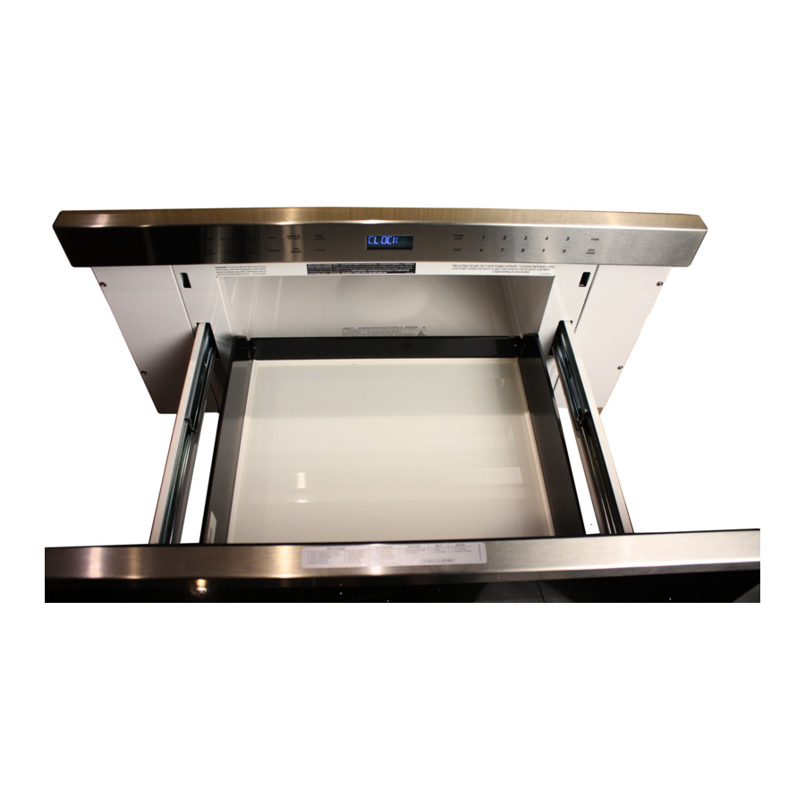
MD24 and MD30 General Information MD24 and MD30 DRAWER MICROWAVE FEATURES • Built-in microwave oven with 950 watts of power • 30” (762mm) model allows microwave to be built in to fit below a Wolf built-in E-Series or M-Series oven • Classic stainless steel finish •... -
Page 6: Cookware Suggestions
General Information MD24 and MD30 MD24 and MD30 COOKWARE SUGGESTIONS NOTE: Make sure the utensil does not touch the interior walls during cooking. Use these utensils for safe microwave cooking and reheating: • Glass ceramic • Heat-resistant glass • Microwave-safe plastics •... -
Page 7: Installation Information
Installation Information MD24 and MD30 INSTALLATION INFORMATION Below are the Product Safety Labels used in this manual. This section of the manual covers some of the installation issues that a service technician may need to know when servicing a Wolf Microwave Drawer. If additional installation information is needed, after reviewing this section of the manual, please refer to the Installation Guide or contact the Wolf Appliance Customer Care Department. -
Page 8: Clearances And Dimensions Md24
Installation Information MD24 and MD30 Clearances and Dimensions Dimensions shown on this page must be used. Given dimensions provide minimum clearance. NOTES: • The Microwave Drawer can also be installed using an electrical outlet in an adjacent cabinet within the area where the provided electrical cord can reach. - Page 9 Installation Information MD24 and MD30 21 / " (549) " " " POWER CORD (32) (45) CHANNEL (118) " " (384) (372) " " (759) (556) BEHIND FRAME OPEN DRAWER " (419) Figure 2-4. 30” Microwave Drawer Dimensions STANDARD INSTALLATION FLUSH INSET INSTALLATION 22"...
-
Page 10: Controls & Operation
Theory of Operation MD24 and MD30 USER OPERATION CONTROL LOCK Control Lock feature prevents unwanted microwave oven operation. TO LOCK: 1. Touch CONTROL LOCK, then touch START. ‘LOCK ON’ will appear on control panel display. TO UNLOCK: 1. Touch CONTROL LOCK, then touch START. ‘LOCK OFF’ will appear on control panel display. OPEN/CLOSE To open or close drawer, touch OPEN/CLOSE. -
Page 11: Demonstration Mode
Theory of Operation MD24 and MD30 To Restore Cook Time Completion Reminder: 1. Touch SETTINGS three times. 2. Touch START. ‘REMIND SIGNAL ON’ will appear on control panel display. DEMONSTRATION MODE Demonstration mode allows operation to be demonstrated without energizing the High Voltage circuit. To enter Demonstration Mode: 1. -
Page 12: Auto Start
Theory of Operation MD24 and MD30 AUTO START The microwave oven can be programmed to begin cooking automatically at a designated time of day. The clock must be set to correct time for Auto Start to function properly. To use Auto Start: 1. -
Page 13: Beverage
Theory of Operation MD24 and MD30 BEVERAGE The beverage feature will reheat a beverage or prepare hot water for coffee or tea. To use Beverage: 1. Touch BEVERAGE. 2. To reheat beverage: Touch 1 multiple times to select amount in 1/2 cup increments, up to 2 cups. 3. -
Page 14: Off Condition
Theory of Operation MD24 and MD30 DESCRIPTION OF OPERATING SEQUENCE OFF CONDITION 8. When drawer opens from closed position, primary Closing drawer activates door sensing switch and interlock relay (RY2) and secondary interlock switch secondary interlock switch. (Monitor switch contacts open their contacts. -
Page 15: Sensor Cooking Condition
Theory of Operation MD24 and MD30 SENSOR COOKING CONDITION Using SENSOR function, food is cooked without figur- ing time, power level or quantity. When oven senses enough steam from the food, it relays information to its microprocessor which will calculate remaining cooking time and power level needed for best results. - Page 16 Theory of Operation MD24 and MD30 #824820 - Revision A - November, 2013...
-
Page 17: Component Access & Removal
Component Access MD24 and MD30 COMPONENT ACCESS AND REMOVAL This section explains how to adjust, access and remove components in a Microwave Drawer Oven. An attempt has been made to arrange these procedures in such a way as to simulate which components would need to be removed first in order to gain access to other components. -
Page 18: Microwave Measurement Procedure
Component Access MD24 and MD30 MICROWAVE MEASUREMENT PROCEDURE 1. Requirements: A. Microwave leakage limit (Power density limit): The power density of microwave radiation emitted by a microwave oven should not exceed 1mW/cm2 at any point 5cm or more from the external surface of the oven, measured prior to acquisition by a purchaser, and thereafter (through the useful life of the oven), 5 mW/cm2 at any point 5cm or more from the external surface of the oven. -
Page 19: Emergency Opening Of Drawer
Component Access MD24 and MD30 Emergency Opening of Drawer: Accessing Rear Components: If unit is flush mounted and drawer is not opening use 1.Extract ten screws holding Back Cover. (See Figure 4- one of following procedures. 1.Use an angled screw driver or allen key wrench and insert it under bottom middle of drawer to grab the vent opening at bottom of drawer and carefully pull drawer Back cover... -
Page 20: Noise Filter Board Replacement
Component Access MD24 and MD30 6. With drawer closed, adjust latch hook by moving it Noise Filter Board Replacement 1.Disconnect Black and White wire from Noise Filter back and forth, and up and down. In and out play of drawer allowed by upper and lower position of latch Board. -
Page 21: Drawer Assembly And Choke Removal
Component Access MD24 and MD30 After Adusting Latch Hook - Check the following. Drawer Support Angle Removal 1.In and out play of drawer remains less than 0.5mm 1.Remove Drawer Assembly and Choke Cover as stated when in latched position. First check upper position of in prior section. -
Page 22: Auto Drawer Gear Removal
Component Access MD24 and MD30 Door Latch Removal 1.Follow "DRAWER ASSEMBLY AND CHOKE REMOVAL" 2.Lay door panel and door frame assembly front down on a protective surface. 3.Extract six screws holding door panel to door frame. 4.With door frame removed, unhook latch spring, then extract screw. -
Page 23: Rack Gear/Oil Damper Removal
Component Access MD24 and MD30 Rack Gear/Oil Damper Removal After Reassembly 1.Follow Microwave Drawer disassembly as previously 1.Make sure that drawer sensing switch, third door stated. switch, secondary interlock switch and monitor 2.Open drawer and keep it open. switch are operating properly. 3.To discharge high voltage capacitor, wait for 60 sec- 2.An approved microwave survey meter should be used onds. - Page 24 Component Access MD24 and MD30 #824820 - Revision A - November, 2013...
-
Page 25: Troubleshooting Guide
Troubleshooting Guide MD24 and MD30 TROUBLESHOOTING GUIDE This section of the manual explains the Component Test Procedures. NOTE: Before continuing, please take note of the WARNINGS and CAUTIONS below. • TO AVOID ELECTRIC SHOCK DURING TROUBLESHOOTING, NEVER TOUCH ANY PART OF THE ELECTRI- CAL CIRCUIT WITH HANDS OR UN-INSULATED TOOLS WHILE THE POWER IS CONNECTED. -
Page 26: Troubleshooting Chart
MD24 and MD30 Troubleshooting Guide TROUBLESHOOTING CHART CK = Check / RE = Replace TEST PROCEDURE REFERENCE LETTER Display does not operate properly when STOP/CLEAR key is touched. (Buzzer should sound and ":" or time of day should appear in display.) Oven seems to be operating but little or no heat is produced in oven load. -
Page 27: Control Panel Assembly Test
Troubleshooting Guide MD24 and MD30 TEST PROCEDURES Note: Pictures of the four main boards are at the end of this section. PROCEDURE LETTER COMPONENT TEST CONTROL PANEL ASSEMBLY TEST: Control panel consists of a Piezo Control Panel. Control Panel keyboard consist of two parts;... -
Page 28: Psu-Drawer Board And Relay Test
MD24 and MD30 Troubleshooting Guide PROCEDURE LETTER COMPONENT TEST PSU-DRAWER BOARD and RELAY TEST: 1. Disconnect power supply cord, and then remove outer case. 2. Open door and block it open. 3. Discharge high voltage capacitor. 4. Disconnect leads to the primary of the MD transformer. 5. -
Page 29: Defrost Test
Troubleshooting Guide MD24 and MD30 PROCEDURE LETTER COMPONENT TEST DEFROST TEST: OVEN SHOULD BE FULLY ASSEMBLED BEFORE ATTEMPTING FOLLOWING PROCEDURE. 1. Place one cup of water in center of tray in oven cavity. 2. Close drawer, touch Defrost pad. Then select Steaks/Chops by touching number pad 2. - Page 30 MD24 and MD30 Troubleshooting Guide PROCEDURE LETTER COMPONENT TEST E - continued PSU-DRAWER BOARD FUSE IS OPEN - Continued: 2. Follow troubleshooting guide given below, if indicator does not light up after above check and repairs are finished. • Disconnect power supply cord. •...
-
Page 31: Ah Sensor Test
Troubleshooting Guide MD24 and MD30 PROCEDURE LETTER COMPONENT TEST AH SENSOR TEST: THE OVEN SHOULD BE FULLY ASSEMBLED BEFORE ATTEMPTING THE FOL- LOWING PROCEDURE. Checking the sensor cooking condition 1. The oven should be plugged in at least two minutes before sensor cooking. 2. - Page 32 MD24 and MD30 Troubleshooting Guide PROCEDURE LETTER COMPONENT TEST F - continued TESTING METHOD FOR AH SENSOR: To determine if sensor is defective, the simplest method is to replace it with a new sensor. 1. Disconnect power supply cord, and then disassemble as per “Drawer Microwave Disassembly”...
-
Page 33: Magnetron Assembly Test (Includes Power Output)
Troubleshooting Guide MD24 and MD30 PROCEDURE LETTER COMPONENT TEST MAGNETRON ASSEMBLY TEST: 1. Disconnect power supply cord. 2. Open drawer and keep it open. 3. To discharge high voltage capacitor, wait for 60 seconds. 4. To test for an open filament, isolate magnetron from high voltage circuit. A continuity check across magnetron filament leads should indicate less than 1 ohm. -
Page 34: Thermal Cut-Out Test
MD24 and MD30 Troubleshooting Guide PROCEDURE LETTER COMPONENT TEST THERMAL CUT-OUT TEST: 1. Disconnect power supply cord. 2. Open drawer and keep it open. 3. To discharge high voltage capacitor, wait for 60 seconds. 4. A continuity check across thermal cut-out terminals should indicate a closed circuit unless temperature of the thermal cut-out reaches approximately 293°F(145°C). -
Page 35: Monitor Switch Test
Troubleshooting Guide MD24 and MD30 PROCEDURE LETTER COMPONENT TEST MONITOR SWITCH TEST: 1. Disconnect power supply cord. 2. Open drawer and keep it open. 3. To discharge high voltage capacitor, wait for 60 seconds. 4. Before performing test, make sure that secondary interlock switch is operat- ing, according to above Switch Test Procedure. -
Page 36: Md Transformer Test
MD24 and MD30 Troubleshooting Guide PROCEDURE LETTER COMPONENT TEST MD TRANSFORMER TEST: 1. Disconnect power supply cord. 2. Open drawer and block it open. 3. Discharge high voltage capacitor. 4. Disconnect primary input terminals and measure resistance of the MD trans- former with an ohmmeter. -
Page 37: High Voltage Rectifier Test
Troubleshooting Guide MD24 and MD30 COMPONENT TEST PROCEDURE LETTER N - continued MEASURING POINT INDICATION OF OHM-METER Between N and H 275 - 415Ω Between terminal N and LOAD Short Circuit Between terminal H and LOAD Short Circuit Fuse Short Circuit NOISE FILTER CONTINUED: If fuse is open, replace fuse. -
Page 38: Relay Diode Test
MD24 and MD30 Troubleshooting Guide PROCEDURE LETTER COMPONENT TEST HIGH VOLTAGE CAPACITOR TEST: 1. Disconnect power supply cord, and then remove outer case. 2. Open door and block it open. 3. Discharge high voltage capacitor. 4. If capacitor is open, no high voltage will be available to magnetron. Disconnect input leads and check for short or open between terminals using an ohm meter. - Page 39 Troubleshooting Guide MD24 and MD30 Figure 5-6. CPU-Drawer Board Front and Back Figure 5-7. SW PSU-Drawer Board Monitor Fuse Monitor Fuse Figure 5-8. Noise Filter Board 5-16 #824820 - Revision A - December, 2013...
- Page 40 MD24 and MD30 Troubleshooting Guide 5-17 #824820 - Revision A - December, 2013...
-
Page 41: Wiring Diagrams
Wiring Diagrams MD24 and MD30 MD WIRING SCHEMATIC (OFF CONDITION) #824820 - Revision A - December, 2013... -
Page 42: Md Wiring Diagram
Wiring Diagrams MD24 and MD30 MD WIRING DIAGRAM (SWITCHING POWER SUPPLY) CN201 Power Supply cord 120V 60Hz NOISE FILTER BOARD 5 BLK CN201 OVEN CN101 MAGNETRON THERMAL THERMAL CUT-OUT CN101 CUT-OUT (POWER SUPPLY) CN-A N.C. CN-F MONITOR SWITCH COM. CN-C THIRD DOOR CN-H...
Need help?
Do you have a question about the Wolf MD24 and is the answer not in the manual?
Questions and answers