Table of Contents
Advertisement
Available languages
Available languages
Advertisement
Table of Contents

Summary of Contents for OPTIMUM Maschinen OPTImill F 80
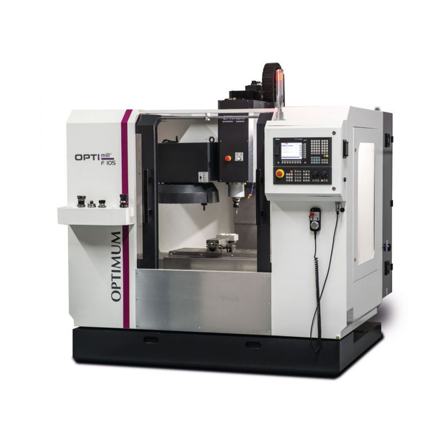
- Page 1 OPTIMUM ® M A S C H I N E N - G E R M A N Y Betriebsanleitung - DE Operating manual - EN Version 1.1.2 CNC Fräsmaschine CNC milling machine Artikel Nr. Part no. 350 1080 Artikel Nr. Part no. 350 1105 Artikel Nr.
- Page 2 OPTIMUM ® M A S C H I N E N - G E R M A N Y Sicherheit Konventionen der Darstellung ........................10 Typschilder .............................10 Sicherheitshinweise (Warnhinweise) ......................11 1.3.1 Gefahren-Klassifizierung ......................11 1.3.2 Weitere Piktogramme ........................12 Bestimmungsgemäße Verwendung......................12 Vernünftigerweise vorhersehbare Fehlanwendung ................13 1.5.1 Vermeidung von Fehlanwendungen....................13 Gefahren, die von der CNC-Maschine ausgehen können.
- Page 3 OPTIMUM ® M A S C H I N E N - G E R M A N Y Transport ..............................33 Aufstellen und Montieren........................35 3.3.1 Anforderungen an den Aufstellort ....................35 Stellplan F80 ............................35 Stellplan F105 ............................37 3.5.1 Maschinenbefestigung ........................
- Page 4 OPTIMUM ® M A S C H I N E N - G E R M A N Y 6.5.3 Bedienung des elektronischen Handrades..................74 6.5.4 Werkzeug einsetzen........................75 6.5.5 Werkstück aufspannen ........................75 6.5.6 Manueller Werkzeugwechsel ......................76 6.5.7 Werkzeugwechsler ........................76 6.5.8 CNC-Maschine ausschalten ......................76 Betriebsarten ............................76 Programmieren ............................77 Programm starten ...........................77...
- Page 5 OPTIMUM ® M A S C H I N E N - G E R M A N Y 13.4 Änderungsinformationen Betriebsanleitung ..................199 13.5 Terminologie/Glossar ........................... 200 13.6 Wiederausfuhr ............................201 13.7 Lagerung .............................. 201 13.8 Mangelhaftungsansprüche / Garantie ....................202 13.9 Entsorgungshinweis / Wiederverwertungsmöglichkeiten: ..............
- Page 6 OPTIMUM ® M A S C H I N E N - G E R M A N Y 2.11 Environmental conditions - operation ....................223 2.12 Environmental conditions - storage ......................224 2.13 Spindle power F80..........................225 2.14 Dimensions milling table F80........................226 2.15 Dimensions milling table F105......................226 2.16...
- Page 7 OPTIMUM ® M A S C H I N E N - G E R M A N Y 5.4.2 Change passwords ........................263 Operation Safety ..............................264 Control and indicating elements ......................264 Operational modes ..........................265 Programming ............................265 Operation of the machine ........................
- Page 8 OPTIMUM ® M A S C H I N E N - G E R M A N Y 11.7.1 Ensuring the backlash .......................299 11.7.2 Worm gear and worm wheel backlash adjustment..............300 11.7.3 Origin mechanism ........................301 11.8 Cooling lubricants and tanks.........................303 11.8.1 Inspection plan for water-mixed cooling lubricants..............304 Brief instruction 808D Milling .....................
- Page 9 Sollten Sie nach dem Lesen dieser Betriebsanleitung noch Fragen haben oder können Sie ein Problem nicht mit Hilfe dieser Betriebsanleitung lösen, setzen Sie sich bitte mit Ihrem Fachhändler oder direkt mit OPTIMUM in Verbindung. Optimum Maschinen Germany GmbH Dr.- Robert - Pfleger - Str. 26 D-96103 Hallstadt...
- Page 10 OPTIMUM ® M A S C H I N E N - G E R M A N Y Sicherheit Dieser Teil der Betriebsanleitung erklärt Ihnen die Bedeutung und die Verwendung der in dieser Betriebsanleitung ver- wendeten Warnhinweise, legt die bestimmungsgemäße Verwendung der CNC-Maschine fest, ...
- Page 11 OPTIMUM ® M A S C H I N E N - G E R M A N Y Sicherheitshinweise (Warnhinweise) 1.3.1 Gefahren-Klassifizierung Wir teilen die Sicherheitshinweise in verschiedene Stufen ein. Die untenstehende Tabelle gibt Ihnen eine Übersicht über die Zuordnung von Symbolen (Piktogrammen) und Signalwörtern zu der konkreten Gefahr und den (möglichen) Folgen.
-
Page 12: Bestimmungsgemäße Verwendung
Die CNC-Maschine ist für den Einsatz in nicht explosionsgefährdeter Umgebung konstruiert und gebaut. Wird die CNC-Maschine anders als oben angeführt eingesetzt, ohne Genehmigung der Firma Bestimmungs Optimum Maschinen Germany GmbH verändert, wird die CNC-Maschine nicht mehr gemäße Ver- wendung bestimmungsgemäß eingesetzt. -
Page 13: Vernünftigerweise Vorhersehbare Fehlanwendung
Wir übernehmen keine Haftung für Schäden aufgrund einer nicht bestimmungsgemäßen Ver- wendung. Wir weisen ausdrücklich darauf hin, dass durch nicht von der Firma Optimum Maschinen Ger- many GmbH genehmigte konstruktive, technische oder verfahrenstechnische Änderungen auch die Garantie oder CE-Konformität erlischt. - Page 14 OPTIMUM ® M A S C H I N E N - G E R M A N Y Gefahren, die von der CNC-Maschine ausgehen können. Die CNC-Maschine wurde auf Betriebssicherheit geprüft. Die Konstruktion und Ausführung ent- sprechen dem Stand der Technik. Dennoch bleibt noch ein Restrisiko bestehen, denn die CNC-Maschine arbeitet mit rotierenden Teilen, ...
- Page 15 CNC-Software SinuTrain. SinuTrain von Siemens ist die ideale Software-Ergänzung zur CNC-Maschine F80 | F105 von Optimum Maschinen Germany GmbH. Als Trainingssoftware unterstützt es die schnelle Einarbeitung in die Bedienung der Steuerung Sinumerik SINUMERIK 808D. Mitarbeiter mit wenig CNC-Erfahrung können mit SinuTrain Grundlagen der DIN-Programmierung lernen und schließlich auch Programme mit SINUMERIK...
- Page 16 OPTIMUM ® M A S C H I N E N - G E R M A N Y Der Betreiber muss das Personal schulen, Pflichten des Betreibers das Personal in regelmäßigen Abständen (mindestens einmal jährlich) unterweisen über - alle die CNC-Maschine betreffenden Sicherheitsvorschriften, - die Bedienung der CNC-Maschine, - die anerkannten Regeln der Technik,...
- Page 17 OPTIMUM ® M A S C H I N E N - G E R M A N Y Die CNC-Maschine hat folgende Sicherheitseinrichtungen: Einen abschließbaren Hauptschalter, Einen Not-Halt-Schlagschalter an der Maschinensteuertafel, am Spindelkopf und am elekt- ronischen Handrad. Eine verriegelte, trennende Schutzeinrichtung um die CNC Fräsmaschine mit Sichtfenstern ...
- Page 18 OPTIMUM ® M A S C H I N E N - G E R M A N Y Abb.1-2: Not-Halt Schlagschalter 1.9.3 Steuerungstechnische Absicherung WARNUNG! Wenn Sie eine Steuerungseinrichtung umgehen, bringen Sie sich und andere an der CNC-Maschine arbeitende Menschen in Gefahr. Verletzungen durch weggeschleuderte Werkzeuge, Werkstücke oder deren Bruchstü- ...
- Page 19 OPTIMUM ® M A S C H I N E N - G E R M A N Y 1.9.4 Sichtfenster aus Polycarbonat Polycarbonat- Sichtfenster, die eine sicherheitskritische Rückhaltefunktion gegenüber wegfliegenden Teilen haben, müssen vom kundenseitig verantwortlichen Personal in regelmä- ßigen Zeitabständen einer Sichtprüfung unterzogen werden, um die betriebliche Sicherheit an der CNC-Maschine zu garantieren.
- Page 20 OPTIMUM ® M A S C H I N E N - G E R M A N Y Funktionsprüfung Einrichtung Prüfung Not-Halt- Nach dem Betätigen eines Not-Halt-Schlagschalters muss die Schlagschalter CNC-Maschine abschalten. Schaltschrankkühlung Die Schaltschrankkühlung muss laufen. trennende Bei geöffneter Schutzeinrichtung darf ein Programmstart nicht Schutzeinrichtung um die möglich sein.
- Page 21 OPTIMUM ® M A S C H I N E N - G E R M A N Y Spannen Sie das Werkstück sicher und fest ein, bevor Sie die CNC-Maschine einschalten. Verändern Sie niemals die Dosierung der Kühlschmiermittelzufuhr während des Betriebs. ...
- Page 22 Überprüfen Sie deren Funktion! 1.15 Unfallbericht Informieren Sie Vorgesetzte und die Firma Optimum Maschinen Germany GmbH sofort über Unfälle, mögliche Gefahrenquellen und „Beinahe“-Unfälle. „Beinahe“-Unfälle können viele Ursachen haben. Je schneller sie berichtet werden, desto schneller können die Ursachen behoben werden.
- Page 23 OPTIMUM ® M A S C H I N E N - G E R M A N Y Die Prüfung vor der ersten Inbetriebnahme ist nicht erforderlich, wenn dem Betreiber vom Her- steller oder Errichter bestätigt wird, dass die elektrischen Anlagen und Betriebsmittel den Bestimmungen der Unfallverhütungsvorschrift entsprechend beschaffen sind, siehe Konfor- mitätserklärung.
-
Page 24: Technische Daten
OPTIMUM ® M A S C H I N E N - G E R M A N Y Technische Daten Die folgenden Daten sind Maß- und Gewichtsangaben und die vom Hersteller genehmigten Maschinendaten. F80 (Advanced) F105 (Advanced) Elektrischer Anschluss Gesamtanschluss 3 x 400V ~ 50Hz 12 KVA 3 x 400V ~ 50Hz 12,5 KVA... - Page 25 OPTIMUM ® M A S C H I N E N - G E R M A N Y F80 (Advanced) F105 (Advanced) Höhe [mm] „3.4 Stellplan F80“ auf „3.5 Stellplan F105“ auf Tiefe [mm] Seite 35 Seite 37 Breite [mm] Gesamtgewicht [kg] 1900...
- Page 26 OPTIMUM ® M A S C H I N E N - G E R M A N Y F80 (Advanced) F105 (Advanced) Luftdruck 700...1060 hPa 2.12 Umgebungsbedingungen - Lagerung Temperatur 5 - 45 °C Technische Daten F80 | F105 Seite 26 Originalbetriebsanleitung Version 1.1.2 vom 2019-05-07...
- Page 27 OPTIMUM ® M A S C H I N E N - G E R M A N Y 2.13 Spindelleistung F80 Technische Daten F80 | F105 Version 1.1.2 vom 2019-05-07 Originalbetriebsanleitung Seite 27...
- Page 28 OPTIMUM ® M A S C H I N E N - G E R M A N Y 2.14 Abmessung Frästisch F80 A-A ( 0,3 ) 2.15 Abmessung Frästisch F105 A-A ( 0,3 ) Technische Daten F80 | F105 Seite 28 Originalbetriebsanleitung Version 1.1.2 vom 2019-05-07...
- Page 29 OPTIMUM ® M A S C H I N E N - G E R M A N Y 2.16 Emissionen Die Lärmentwicklung (Emission) der CNC-Maschine ist unter 80 dB(A). Wenn mehrere Maschinen am Standort der CNC-Maschine betrieben werden, kann die Lär- meinwirkung (Immission) auf den Bediener der CNC-Maschine am Arbeitsplatz 80 dB(A) über- schreiten.
- Page 30 OPTIMUM ® M A S C H I N E N - G E R M A N Y 2.18 Optionale vierte Achse nur F105 808D Advanced Tischdurchmesser [ mm ] Gewicht [ kg ] Zentrumshöhe Tisch vertikal [ mm ] Horizontale Tischhöhe [ mm ] Durchmesser Durchgangsbohrung [ mm ] Durchmesser Zentrierabsatz [ mm ]...
- Page 31 OPTIMUM ® M A S C H I N E N - G E R M A N Y max. radiale Belastung F = 5,8 KN F x L =147 Nm F x L =196 Nm max. Masseträgheitsmoment 0,2 kg x cm x sec Drehtisch CNC 120-R Version 1.1.2 vom 2019-05-07...
- Page 32 OPTIMUM ® M A S C H I N E N - G E R M A N Y CNC 120-R Seite 32 Originalbetriebsanleitung Version 1.1.2 vom 2019-05-07...
-
Page 33: Montage Und Inbetriebnahme
OPTIMUM ® M A S C H I N E N - G E R M A N Y Montage und Inbetriebnahme INFORMATION Die CNC-Maschine ist komplett vormontiert. Die Anlieferung erfolgt in einer Holzkiste. Lieferumfang Vergleichen Sie den Lieferumfang mit der beiliegenden Packliste. Kontrollieren Sie unverzüglich nach Erhalt der CNC-Maschine den Zustand und reklamieren Sie sofort eventuelle Schäden beim letzten Transportführer, auch dann, wenn die Verpackung nicht beschädigt ist. - Page 34 OPTIMUM ® M A S C H I N E N - G E R M A N Y Demontieren Sie das Sechskantmuttern, mit denen die Maschine auf der Holzpalette befes- tigt ist. Heben Sie die CNC-Maschine mit einer geeigneten Fördereinrichtung, z.B. Gabelstapler vorsichtig von der Holzpalette.
- Page 35 OPTIMUM ® M A S C H I N E N - G E R M A N Y Aufstellen und Montieren 3.3.1 Anforderungen an den Aufstellort Gestalten Sie den Arbeitsraum um die CNC-Maschine entsprechend der örtlichen Sicherheits- Vorschriften. Der Arbeitsraum für die Bedienung, Wartung und Instandsetzung darf nicht eingeschränkt wer- den.
- Page 36 Verankerte Montage - F80 Verwenden Sie die verankerte Montage um eine steife Verbindung mit dem Untergrund zu erreichen. Eine verankerte Montage ist immer dann sinnvoll, wenn große Teile bis zur Maximalkapazität der CNC-Maschine bearbeitet werden sollen. Door Door open Door open open 1368...
- Page 37 OPTIMUM ® M A S C H I N E N - G E R M A N Y Stellplan F105 1055 A-A ( 0,05 ) 1520 2164 Abb.3-4: Stellplan 3.5.1 Maschinenbefestigung Verankerungsfreie Montage Verwenden Sie -falls erforderlich- Schwingelemente für den Maschinenunterbau. ...
- Page 38 Verankerte Montage - F105 Verwenden Sie die verankerte Montage um eine steife Verbindung mit dem Untergrund zu erreichen. Eine verankerte Montage ist immer dann sinnvoll, wenn große Teile bis zur Maximalkapazität der CNC-Maschine bearbeitet werden sollen. Door Door Door open open open 1546...
- Page 39 OPTIMUM ® M A S C H I N E N - G E R M A N Y 3.5.2 Ausrichten der Maschine Richten Sie die CNC-Maschine am Frästisch mit einer Maschinenwasserwaage aus. Ver- wenden Sie die Stellschrauben, um den erforderlichen Höhenausgleich durchzuführen. „Maschinenbefestigung“...
- Page 40 OPTIMUM ® M A S C H I N E N - G E R M A N Y 3.6.2 Montage der Kühlschmiermittelpumpen Schliessen Sie die Anschlussstecker der Kühlschmiermittelpumpen, sowie die Kühlschmier- mittelschläuche des Kühlschmiermittelbehälters an. Achten Sie darauf das die Steckver- bindungen korrekt hergestellt sind.
- Page 41 OPTIMUM ® M A S C H I N E N - G E R M A N Y 3.6.4 Anschluss Druckluftversorgung Schließen Sie die Druckluftversorgung mit mindestens 6,5 bar am Druckluftanschluss der Druckluft - Wartungseinheit an. Stellen Sie über die Einstellschraube der Wartungseinheit einen Druck von 6,3 bar ein. Druckschalter Druckluftanschluss Manometer...
- Page 42 OPTIMUM ® M A S C H I N E N - G E R M A N Y Druckluftschema F80 Zylinder Werkzeugwechsler Drosselventil Zylinder Werkzeugspannung Drosselventil Wegeventil Wegeventil entlüftungsventil Druckschalter Wartungseinheit Abb.3-10: F80 Montage und Inbetriebnahme F80 | F105 Seite 42 Originalbetriebsanleitung Version 1.1.2 vom 2019-05-07...
- Page 43 OPTIMUM ® M A S C H I N E N - G E R M A N Y Druckluftschema F105 Zylinder Werkzeugwechsler Drosselventil Zylinder Werkzeugspannung Drosselventil Wegeventil Bremse optionaler Drehtisch Schnell- Wegeventil entlüftungsventil Druckschalter Wartungseinheit Abb.3-11: F105 Erste Inbetriebnahme 3.7.1 Kühlschmiermittel auffüllen INFORMATION...
- Page 44 Die Auswahl der Kühlschmierstoffe und Bettbahnöle, Schmieröle bzw. Fette sowie deren Pflege wird vom Maschinenanwender bzw. Betreiber bestimmt. Die Optimum Maschinen Germany GmbH kann daher für Maschinenschäden die durch ungeeignete Kühlschmierstoffe und Schmierstoffe sowie durch mangelhafte Pflege und War- tung des Kühlschmierstoffes verursacht wurden, nicht verantwortlich gemacht werden. Bei Pro- blemen mit dem Kühlschmierstoff und Bettbahnöl bzw.
- Page 45 OPTIMUM ® M A S C H I N E N - G E R M A N Y Funktionstests und Kontrollen Drehrichtung Kühlmittelpumpe Prüfen Sie die Drehrichtung der CNC-Maschine, es muss sich ein rechtes Drehfeld ergeben. Tauschen Sie zwei von drei Phasen-Leitern untereinander aus, wenn die Drehrichtung falsch sein sollte.
-
Page 46: Elektrischer Anschluss
OPTIMUM ® M A S C H I N E N - G E R M A N Y 3.9.2 Funktion Datensicherung Die CNC-Steuerung verfügt lediglich über einen „flüchtigen Arbeitsspeicher“, der spätestens nach drei Wochen seinen Inhalt verliert. Aus diesem Grund ist es nach der Inbetriebnahme der Maschine bzw. der Maschinensteue- rung unbedingt erforderlich, eine Datensicherung durchzuführen. - Page 47 OPTIMUM ® M A S C H I N E N - G E R M A N Y ACHTUNG! Frequenzumrichter (Antriebsregler) können den FI-Schutzschalter Ihrer elektrischen Versorgung auslösen. Um eine Funktionsstörung zu vermeiden benötigen Sie entweder einen pulsstromsensitiven, oder einen allstromsensitiven FI-Schutzschalter. ACHTUNG! Achten Sie unbedingt darauf, dass alle 3 Phasen (L1, L2, L3) und das Erdungskabel richtig angeschlossen sind.
- Page 48 OPTIMUM ® M A S C H I N E N - G E R M A N Y 3.11 Geregelte Antriebe in Verbindung mit Fehlerstrom-Schutzeinrichtungen Drehzahlgeregelte Antriebe gehören im Maschinen- und Anlagenbau zu den Standardbetriebs- mitteln und erledigen verschiedene Aufgaben. Gegenüber einem einfachen Motor erfordern die elektronischen Gleich- bzw.
- Page 49 OPTIMUM ® M A S C H I N E N - G E R M A N Y über den Stecker geführt wird, und mindestens dem Querschnitt des Kabels im Stecker ent- spricht. Da durch den Frequenzumrichter im Schutzerdungsleiter ein Gleichstrom hervorgerufen wer- den kann, müssen, wenn im Netzwerk eine vorgeschaltete Fehlerstrom-Schutzeinrichtung (ELCB/RCD) erforderlich ist, die folgenden Hinweise beachtet werden: Um eine Funktionsstörung zu vermeiden, benötigen Sie einen allstrom-sensitiven FI-Schutz-...
- Page 50 OPTIMUM ® M A S C H I N E N - G E R M A N Y 3.12 Befestigung des optionalen Drehtisches - vierte Achse - auf dem Maschinentisch Entfernen Sie zuerst den Oxidationsschutz und setzen Sie dann den Drehtisch auf den Maschinentisch.
- Page 51 OPTIMUM ® M A S C H I N E N - G E R M A N Y Allgemeine Informationen CNC Geometrieverrechnung Zur Ausführung von Werkzeug- Bewegungen am Werkstück muss jede augenblickliche Ist- Position der CNC-gesteuerten Achsen gemessen, der Meßwert auf einen maschinenfesten Nullpunkt bezogen und mit einer durch das Programm vorgegebenen Soll-Position verglichen werden.
- Page 52 OPTIMUM ® M A S C H I N E N - G E R M A N Y 4.2.2 Polarkoordinatensystem Im kartesischen Koordinatensystem wird ein Punkt z.B. durch seine X- und Y- Koordinate beschrieben. Bei rotationssymetrischen Konturen, z. B. kreisförmigen Bohrbildern sind die benötigten Koordinaten nur mit erheblichen Aufwand zu berechnen.
- Page 53 OPTIMUM ® M A S C H I N E N - G E R M A N Y 4.2.5 Drehachsen und Nebenachsen NC- Maschinen mit drehbarem Tisch oder Schwenkkopf Drehachsen: A B C positive Drehung um X, Y, Z (Rechte- Hand- Regel) NC- Maschinen mit mehreren Vorschubachsen Nebenachsen: U V W parallel zu X-,Y-,Z- Achse...
- Page 54 OPTIMUM ® M A S C H I N E N - G E R M A N Y Am rechtwinkligen Dreieck wird der rechte Winkel durch einen im Winkel liegenden Viertelkreis und einen Punkt dargestellt. Im rechtwinkligen Dreieck gilt: Am rechtwinkligen Dreieck läßt sich die Länge einer fehlenden Seite berechnen, wenn die anderen Seitenlängen bekannt sind.
- Page 55 OPTIMUM ® M A S C H I N E N - G E R M A N Y Bedienoberfläche, Maschinensteuertafel Bildschirmaufbau Auszug aus dem Programmier- und Bedienhandbuch "SINUMERIK 808D OPM Operation" Abb.5-1: Bildschirmeinteilung Status Bereich Anwendungsbereich Aktiver Bedienbereich Istwerte Fenster Aktive Betriebsart T (W), F(V), S Fenster Betriebssystem Fenster mit Programm-Satz...
- Page 56 OPTIMUM ® M A S C H I N E N - G E R M A N Y Bedienelemente CNC Bedientafel Abb.5-2: CNC Bedientafel Bedienelemente der CNC Bedientafel Auszug aus dem Programmier- und Bedienhandbuch "SINUMERIK 808D OPM Operation" Beschreibung Vertikale und horizontale Softkeys Ruft Menüfunktionen auf Zurück Taste...
- Page 57 OPTIMUM ® M A S C H I N E N - G E R M A N Y Bedienelemente der CNC Bedientafel Auszug aus dem Programmier- und Bedienhandbuch "SINUMERIK 808D OPM Operation" Beschreibung Steuerungstasten SHIFT- Taste (Umschalttaste) CTRL-Taste (Strg-Taste) ALT-Taste Leertaste Rücktaste...
- Page 58 OPTIMUM ® M A S C H I N E N - G E R M A N Y Bedienelemente der CNC Bedientafel Auszug aus dem Programmier- und Bedienhandbuch "SINUMERIK 808D OPM Operation" Beschreibung Menüfunktionstaste Öffnet die Hauptseite des Bedienungsassistenten. Hilfe-Taste Ruft die kontextsensitive Hilfe für das ausgewählte Fenster, Alarm, Nachricht, Maschinendaten, Settingdaten, oder Endbenutzer-...
-
Page 59: Usb Schnittstelle
OPTIMUM ® M A S C H I N E N - G E R M A N Y Bedienelemente der CNC Bedientafel Auszug aus dem Programmier- und Bedienhandbuch "SINUMERIK 808D OPM Operation" Beschreibung Tasten Bedienbereich Öffnet den "Maschinen" Bedienbereich Öffnet den "Programm"... - Page 60 OPTIMUM ® M A S C H I N E N - G E R M A N Y 5.2.1 Tastenkombinationen Auszug aus dem Programmier- und Bedienhandbuch "SINUMERIK 808D OPM Operation" Element Beschreibung <ALT> + <X> Öffnet den "Maschinen" Bedienbereich <ALT>...
- Page 61 OPTIMUM ® M A S C H I N E N - G E R M A N Y Bedienelemente der Maschinensteuertafel Abb.5-3: Maschinensteuertafel Bedienelemente der Maschinensteuertafel Element Funktion Antriebsspannung Drucktaster mit Leuchtmelder • Leuchtmelder an, Antriebsspannung aktiv • Leuchtmelder aus, Antriebsspannung deaktiviert Auszug aus dem Programmier- und Bedienhandbuch "SINUMERIK 808D OPM Operation"...
- Page 62 OPTIMUM ® M A S C H I N E N - G E R M A N Y Auszug aus dem Programmier- und Bedienhandbuch "SINUMERIK 808D OPM Operation" Element Beschreibung Handrad-Taste (mit einer LED-Statusanzeige) Steuert die Achsbewegung mit dem elektronischen Handrad. Werkzeug-Nummer Anzeige Zeigt die aktuelle Werkzeugnummer Betriebsarten-Tasten (alle mit LED-Statusanzeigen)
- Page 63 OPTIMUM ® M A S C H I N E N - G E R M A N Y Auszug aus dem Programmier- und Bedienhandbuch "SINUMERIK 808D OPM Operation" Element Beschreibung Benutzerdefinierte Tasten (alle mit LED-Statusanzeigen) Taste Maschinenleuchte Betätigung in jeder Betriebsart schaltet die Maschinenleuchte an / aus.
- Page 64 OPTIMUM ® M A S C H I N E N - G E R M A N Y Auszug aus dem Programmier- und Bedienhandbuch "SINUMERIK 808D OPM Operation" Element Beschreibung Vorwärtsdrehung des Späneförderers (nur aktiv bei JOG) Durch Drücken dieser Taste in jeder Betriebsart startet die Vorwärtsdrehung des Späneförderers.
- Page 65 OPTIMUM ® M A S C H I N E N - G E R M A N Y Auszug aus dem Programmier- und Bedienhandbuch "SINUMERIK 808D OPM Operation" Element Beschreibung X Achstaste Verfährt die X-Achse in die positive Richtung. X Achstaste Verfährt die X-Achse in die negative Richtung.
- Page 66 OPTIMUM ® M A S C H I N E N - G E R M A N Y Auszug aus dem Programmier- und Bedienhandbuch "SINUMERIK 808D OPM Operation" Element Beschreibung Startet die Spindel im Uhrzeigersinn Schalter Spindeldrehzahlkorrektur Verändert die Spindeldrehung auf die angegebene Spindeldrehzahlkorrektur.
- Page 67 OPTIMUM ® M A S C H I N E N - G E R M A N Y Schutzstufe Gesperrt von Bereich Siemens Passwort Reserviert von Siemens Hersteller Passwort Maschinenhersteller Reserviert 3 - 6 Endbenutzer Passwort Endbenutzer (Standard Password: "CUSTOMER") Ohne Passwort Endbenutzer Schutzstufe 1...
- Page 68 OPTIMUM ® M A S C H I N E N - G E R M A N Y Schritt 2 Geben Sie das Endbenutzer oder Hersteller-Passwort ein. Passwort setzen Ändern Sie das Endbenutzer oder Hersteller-Passwort. Passwort ändern ...
-
Page 69: Bedienung
OPTIMUM ® M A S C H I N E N - G E R M A N Y Bedienung Sicherheit Nehmen Sie die CNC-Maschine nur unter folgenden Voraussetzungen in Betrieb: Der technische Zustand der CNC-Maschine ist einwandfrei. Die CNC-Maschine wird bestimmungsgemäß eingesetzt. ... - Page 70 OPTIMUM ® M A S C H I N E N - G E R M A N Y Signalleuchte Pos. Farbe Bedeutung Leuchtet bei Betätigung des Not Aus- Schlagschalters Leuchtet bei einer Störung bzw. im Einrichtebetrieb wie z. B. Orange geöffnete Schutzumhausung Leuchtet in der Betriebsart „Automatikmodus“...
- Page 71 OPTIMUM ® M A S C H I N E N - G E R M A N Y Bedienung der Maschine 6.5.1 CNC-Maschine einschalten Schalten Sie den Hauptschalter ein. „Hauptschalter abschließbar“ auf Seite 17 Warten Sie, bis die Steuerung vollständig hochgefahren ist. ...
- Page 72 OPTIMUM ® M A S C H I N E N - G E R M A N Y 6.5.2 Referenzfahren nach dem Einschalten INFORMATION Ein Referenzpunktfahren ist nicht erforderlich, wenn Ihre Maschine mit ABS-Encodern konfiguriert ist (808D ADVANCED). Wenn Ihre Maschine mit INC Encodern ausgestattet ist (808D), muss nach dem Einschalten zuerst ein Referenzpunktfahren durchgeführt werden! Nach dem Einschalten muss die F80 | F105 zuerst referenziert werden.
- Page 73 OPTIMUM ® M A S C H I N E N - G E R M A N Y Verfahren Sie jede Achse zum Maschinennullpunkt bis das "Refe- renziert Symbol" an der jeweiligen Achse erscheint. Nach Abschluss des Vorgangs "Refe- renzierung der Achsen"...
- Page 74 OPTIMUM ® M A S C H I N E N - G E R M A N Y 6.5.3 Bedienung des elektronischen Handrades Das elektronische Handrad kann immer dann verwendet werden, wenn die CNC-Maschine referenziert ist, die LED an der Taste <HANDWHEEL> leuchtet. ...
-
Page 75: Werkzeug Einsetzen
OPTIMUM ® M A S C H I N E N - G E R M A N Y 6.5.4 Werkzeug einsetzen INFORMATION Bevor Sie ein CNC Programm ausführen können, muss mindestens ein Werkzeug im Werkzeugspeicher angelegt und vermessen worden sein. ... - Page 76 OPTIMUM ® M A S C H I N E N - G E R M A N Y 6.5.6 Manueller Werkzeugwechsel ACHTUNG! Halten Sie Ihr Werkzeug fest, wenn Sich ein Werkzeug in der Spindel befindet. Betätigen Sie den Drucktaster "Türe Öffnen / Schließen" und Öffnen Sie die Schiebetür. ...
-
Page 77: Programm Starten
OPTIMUM ® M A S C H I N E N - G E R M A N Y Programmieren Gehen Sie für die weiteren Arbeitsschritte wie in den Handbüchern „Bedienung und Pro- grammierung Fräsen“ zur „SINUMERIK 808D" beschrieben vor. Hand- bzw. - Page 78 OPTIMUM ® M A S C H I N E N - G E R M A N Y Datenschnittstellen und Stromabnahme Beim Anschluss von Datenschnittstellen ist zu beachten, dass das Datenkabel auf kürzestem Weg zur Schnittstelle der Steuerung geführt wird. Die Kabelführung kann an den Meßsys- temleitungen entlang geführt werden.
- Page 79 OPTIMUM ® M A S C H I N E N - G E R M A N Y Al-Legierung Stahl Grauguss ausgehär- Werkzeugdurchmesser 10 - 25 m/min 10 - 22 m/min 150 - 350 [ mm ] Walzen- und m/min Walzenstirnfräser Drehzahl [...
- Page 80 OPTIMUM ® M A S C H I N E N - G E R M A N Y Bei rostfreien Werkstoffen (z.B. VA- oder NIRO-Bleche) nicht ankörnen, da sich der Werk- stoff verfestigt und die Bohrer schneller stumpf werden. Die Werkstücke müssen immer unnachgiebig und stabil niedergespannt werden (Schraub- ...
- Page 81 OPTIMUM ® M A S C H I N E N - G E R M A N Y 6.11 Zentralschmiersystem Werkseinstellung Notieren Sie hier die Werkseinstellung vor einer Änderung Laufzeit [ Sekunden ] Intervall Zeit [ Minuten ] Betriebsmodus Druckeinstellung 2,5 MPa Laufzeit = Zeitdauer mit der die Pumpe die Schmierstellen versorgt.
- Page 82 OPTIMUM ® M A S C H I N E N - G E R M A N Y 6.12 Einstellen der Schmierölmenge an der Zentralschmierung WGKX-1 DRB-215Y Bedienfeld DRB-225Y Bedienfeld 6.12.1 WGKX-4 und WGKX-5 Zeitprogrammierung Pumpe in Betrieb, leuchtet grün LED Status - Minuten oder Sekunden Pumpe nicht in Betrieb, Anzeige erlischt.
- Page 83 OPTIMUM ® M A S C H I N E N - G E R M A N Y In der Ablauffolge erwartet die WGKX-5 Steuerung jetzt die Eingabe der Einstellung des Betriebsmodi. Der Betriebsmodus wird durch die Auswahl des Zustands der gelben LED gesetzt und mit der "Enter Taste"...
- Page 84 OPTIMUM ® M A S C H I N E N - G E R M A N Y Einstellung der Steckbrücken Werkseinstellung Einschaltdauer (Sekunden) Intervall (Minuten) nicht zulässig INFORMATION Die Werkseinstellung beträgt 75 Minuten als Pause zwischen den Schmierzyklen und 30 Sekunden für die Dauer des Schmierzyklus.
- Page 85 OPTIMUM ® M A S C H I N E N - G E R M A N Y 6.13 CNC Drehtisch Schnittgeschwindigkeitstabelle Das direkte Anweisungssystem mit dem F-Code wird für Anwei- sungen von Vorschubgeschwindigkeiten des CNC-Drehtisches (Bewegung in Grad pro Minute), wie folgt verwendet. Beispiel: F100 = 100 °/min = 0,28 1/min Beziehung zwischen dem Vorschub von Werkzeug und einem Kreis-...
- Page 86 OPTIMUM ® M A S C H I N E N - G E R M A N Y 6.13.1 Beispielprogramm Das Werkstück besitzt einen Durchmesser von 50mm. 1. Fräsen von 5 Flächen am Ende des Werkstücks. 2. Spiralfräsen. 360° 300°...
- Page 87 OPTIMUM ® M A S C H I N E N - G E R M A N Y M - Code Liste, M Funktionen M-Funktionen bei Fräsmachinen nach Funktion Aufheben einer Verriegelung Funktion Programmierter Halt Wahlweiser Halt Programmende Start der Frässpindel in positiver Richtung (rechtsdrehend) Start der Frässpindel in negativer Richtung (linksdrehend)
- Page 88 OPTIMUM ® M A S C H I N E N - G E R M A N Y Funktion Funktion G-Funktionen nach PAL Verfahren im Eilgang Linearinterpolation im Arbeitsgang Kreisinterpolation im Uhrzeigersinn Kreisinterpolation gegen den Uhrzeiger- sinn Verweildauer Genauhalt Verfahren im Eilgang in Polarkoordinaten Linearinterpolation mit Polarkoordinaten Kreisinterpolation im Uhrzeigersinn mit...
- Page 89 OPTIMUM ® M A S C H I N E N - G E R M A N Y Hinweise, Meldungen und Fehlermeldungen Auf der Bedientafel werden alle Meldungen und Alarme als Klartext angezeigt. Der Alarmtext enthält das Datum, die Zeit und ein entsprechendes Symbol für das Löschkriterium. Alarme und Meldungen werden getrennt nach folgenden Kriterien angezeigt: Alarme und Meldungen im Teileprogramm.
- Page 90 OPTIMUM ® M A S C H I N E N - G E R M A N Y 700033 Mag.dreh, fehlgeschl: Magazin/Spindel nicht bereit 700034 Gesuchte T-Nr. nicht gleich programmierter T-Nr. 700035 Timeout Spindelpositionierung auf Ausspannposition 700036 Timeout Spindelpositionierung auf Einspannposition 700037 Do not move MGZ when Z axis under the tool change pos.
- Page 91 OPTIMUM ® M A S C H I N E N - G E R M A N Y Problembehebungen 8.1.1 Problem Werkzeugwechsler VORSICHT! Die Frässpindel muss sich oberhalb des Werkzeugwechslers befinden, andernfalls ver- ursachen Sie durch den nachfolgend beschriebenen Vorgang eine Beschädigung der Maschine.
- Page 92 OPTIMUM ® M A S C H I N E N - G E R M A N Y SINUMERIK 808 D Die komplette Sinumerik 808D Dokumentation setzt sich aus den nachfolgend genannten Handbüchern zusammen, die von der Siemens Webseite geladen werden können. https://support.industry.siemens.com/cs/products?dtp=Manual&mfn=ps&pnid=14581&lc=de- Handbücher die für den Bediener, CNC Programmierer und auch für das Wartungs- und Instandsetzungspersonal der F80 | F105 erforderlich sind.
- Page 93 OPTIMUM ® M A S C H I N E N - G E R M A N Y SINUMERIK 808 D Advanced Die komplette Sinumerik 808D Advanced Dokumentation setzt sich aus den nachfolgend genannten Handbüchern zusammen, die sich am Ende dieser Betriebsanleitung befinden oder der Maschine separat beiliegen.
- Page 94 OPTIMUM ® M A S C H I N E N - G E R M A N Y Instandhaltung Im diesem Kapitel finden Sie wichtige Informationen zur Inspektion Wartung Instandsetzung der CNC-Maschine. ACHTUNG! regelmäßige, sachgemäß ausgeführte Instandhaltung eine wesentliche...
- Page 95 Die Auswahl der Kühlschmierstoffe und Bettbahnöle, Schmieröle bzw. Fette sowie deren Pflege wird vom Maschinenanwender bzw. Betreiber bestimmt. Die Optimum Maschinen Germany GmbH kann daher für Maschinenschäden die durch ungeeignete Kühlschmierstoffe und Schmierstoffe sowie durch mangelhafte Pflege und War- tung des Kühlschmierstoffes verursacht wurden, nicht verantwortlich gemacht werden. Bei Pro- blemen mit dem Kühlschmierstoff und Bettbahnöl bzw.
- Page 96 OPTIMUM ® M A S C H I N E N - G E R M A N Y 11.2 Sicherheit WARNUNG! Die Folgen von unsachgemäß ausgeführten Wartungs- und Instandsetzungsarbeiten können sein: Schwerste Verletzungen von Personen, die an der CNC-Maschine arbeiten, ...
- Page 97 OPTIMUM ® M A S C H I N E N - G E R M A N Y Check Intervall Was? Wie? „Sicherheitsüberprüfung“ auf Seite 19 Reinigen Sie die Polycarbonat- Sichtfenster mit einem geeigneten Reinigungsmittel. Reinigen „Druckluft Wartungseinheit entwässern“...
- Page 98 OPTIMUM ® M A S C H I N E N - G E R M A N Y Check Intervall Was? Wie? Zustandskontrolle Auf Flüssigkeitsstand, Konzentration, pH Wert, Füllstandskontrolle Bakterien und Pilzbefall überprüfen. PH Wert kontrollieren, falls erforderlich Kühl- Schmiermittel austauschen.
- Page 99 OPTIMUM ® M A S C H I N E N - G E R M A N Y Check Intervall Was? Wie? Kontrollieren der Werkzeugwech- Durch manuelles Wechseln selfunktion. Positionierung Reinigen Sie die Spänewannen der Kühlschmier- Reinigen mitteleinrichtung. ...
- Page 100 OPTIMUM ® M A S C H I N E N - G E R M A N Y 11.3.1 Reinigung und Austausch der Polycarbonat- Sichtfenster WARNUNG! Die Polycarbonat- Sichtfenster gehören zur Sicherheitseinrichtung an Ihrer CNC- Maschine. Beschädigte, verkratzte oder sogar gebrochene Polycarbonat- Sichtfenster müssen umgehend ausgetauscht werden.
- Page 101 OPTIMUM ® M A S C H I N E N - G E R M A N Y 11.4 Verriegelungsschalter Schiebetür Der Verriegelungsschalter läßt sich für Instandhaltungs- und Wartungszwecke mechanisch entriegeln. Führen Sie eine Sicherheitsüberprüfung durch, wenn Sie den Verriegelungsschalter ...
- Page 102 Führt Ihr qualifiziertes Fachpersonal die Reparaturen durch, so muss es die Hinweise dieser Betriebsanleitung beachten. Die Firma Optimum Maschinen Germany GmbH übernimmt keine Haftung und Garantie für Schäden und Betriebsstörungen als Folge der Nichtbeachtung dieser Betriebsanleitung. Verwenden Sie für die Reparaturen nur einwandfreies und geeignetes Werkzeug, ...
- Page 103 OPTIMUM ® M A S C H I N E N - G E R M A N Y 11.7 Wartung optionale vierte Achse Öleinlass Signal geklemmt, gelöst Motorabdeckung Platte Druckluftanschluss Tischklemmung Getriebekasten Servomotor CNC 120-R Version 1.1.2 vom 2019-05-07 Originalbetriebsanleitung Seite 103...
- Page 104 OPTIMUM ® M A S C H I N E N - G E R M A N Y Check Intervall Was? Wie? Tauschen Sie das Schmiermittel alle 6 Monate im normalen Betrieb aus. Tauschen Sie das Schmiermittel alle 3 Monate bei einem Dauerbetrieb aus.
- Page 105 OPTIMUM ® M A S C H I N E N - G E R M A N Y 11.7.2 Spieleinstellung am Schneckengetriebe und Schneckenrad Lassen Sie das Schmieröl über die Entleerungsöffnung aus dem Drehtisch ab. Entfernen Sie die Rückabdeckung der Schneckenwelle. ...
- Page 106 OPTIMUM ® M A S C H I N E N - G E R M A N Y 11.7.3 Nullpunktmechanismus INFORMATION Der CNC Drehtisch mit den zugehörigen NC Daten in der Steuerung ist werkseitig eingestellt, und sollte nur bei Winkelfehlern nach einem Austausch von Teilen überprüft und eingestellt werden.
- Page 107 OPTIMUM ® M A S C H I N E N - G E R M A N Y 6. Bitte wiederholen Sie die Schritte 3 ~ 5 erneut und stellen Sie sicher, das der Kompensa- tionswert in der horizontalen T-Nut, die den Bewegungswinkel vom Nullpunktanschlag dar- stellt, mit einer Messuhr gemessen werden kann.
- Page 108 OPTIMUM ® M A S C H I N E N - G E R M A N Y 11.8 Kühlschmierstoffe und Behälter VORSICHT! Der Kühlschmierstoff kann Erkrankungen auslösen. Ein direkter Hautkontakt mit Kühlschmierstoff oder mit Kühlschmierstoff behafteten Teilen ist zu vermeiden. Kühlschmierstoff-Kreisläufe und Behälter für wassergemischte Kühlschmierstoffe müssen nach Bedarf, mindestens jedoch jährlich oder nach jedem Wechsel des Kühlschmierstoffes voll- ständig entleert, gereinigt und desinfiziert werden.
- Page 109 OPTIMUM ® M A S C H I N E N - G E R M A N Y 11.8.1 Prüfplan für wassergemischte Kühlschmierstoffe Firma: Nr.: Datum: Verwendeter Kühlschmierstoff: zu prüfende Größe Prüfmethoden Prüfintervalle Maßnahmen, Erläuterungen wahrnehmbare Aussehen, Geruch täglich Ursachen suchen und beseitigen, Veränderungen z.B.
- Page 110 OPTIMUM Vorbereitung Kurzanleitung 808D Fräsen M A S C H I N E N - G E R M A N Y Kurzanleitung 808D Fräsen Theoretische Grundlagen Es sind Grundkenntnisse in der Programmierung zum Fräsen erforderlich PPU Funktion bevor Sie an einer Maschine arbeiten! der Tastatur Die Informationen in dieser Kurzanleitung enthalten lediglich allgemeine Beschreibungen bzw.
- Page 111 OPTIMUM Vorbereitung Kurzanleitung 808D Fräsen M A S C H I N E N - G E R M A N Y Benutzer- schnittstelle Verfahrachsen Achsen Verfahrtasten Die 808D Maschinensteuertafel (MCP) wird verwendet, um Achsen manuell zu steuern. Die Maschine kann mit den entsprechenden Tasten bewegt werden.
- Page 112 OPTIMUM Vorbereitung Kurzanleitung 808D Fräsen M A S C H I N E N - G E R M A N Y ABLAUF Maschinen- koordinaten- Die Verwendung von Passwörtern stellt sicher, das nur Passwörter system berechtigte Benutzer auf das System zugreifen können. Tätigkeiten wie "Grundlegende Bedienung", "Erweiterte Bedienung"...
- Page 113 OPTIMUM Einschalten und Referenzieren Kurzanleitung 808D Fräsen M A S C H I N E N - G E R M A N Y Einschalten und Referenzieren ABLAUF Beschreibung Einschalten Einschalten In diesem Abschnitt wird beschrieben, wie die Maschine eingeschaltet und referenziert der Maschine Funktion der wird.
- Page 114 OPTIMUM Einschalten und Referenzieren Kurzanleitung 808D Fräsen M A S C H I N E N - G E R M A N Y ABLAUF MCP Modus Referenzpunkt Ein Referenzpunktfahren ist nicht erforderlich, Wechseln fahren der Nach Abschluss des Referenziervorgangs für wenn Ihre Maschine mit ABS-Encodern konfiguriert Maschine alle Achsen erscheint das Referenziert Symbol...
- Page 115 OPTIMUM Werkzeug Einstellung Kurzanleitung 808D Fräsen M A S C H I N E N - G E R M A N Y Werkzeug Einstellung ABLAUF Beschreibung Werkzeug Dieser Abschnitt beschreibt das Erstellen und Einrichten von Werkzeugen. Es muss zuerst ein Werkzeug angelegt und erstellen gemessen werden, bevor das Programm Inhalt...
- Page 116 OPTIMUM Werkzeug Einstellung Kurzanleitung 808D Fräsen M A S C H I N E N - G E R M A N Y ABLAUF Es muss zuerst ein Werkzeug angelegt und Werkzeug- ausgewählt sein, bevor eine Werkzeugschneide schneide Schritt 2 erstellt werden kann.
- Page 117 OPTIMUM Werkzeug Einstellung Kurzanleitung 808D Fräsen M A S C H I N E N - G E R M A N Y ABLAUF Werkzeug in die Schritt 2 Spindel Es muss zuerst ein Werkzeug im System einwechseln angelegt sein, bevor es in die aktive Position Eine neue Schneide kann auf diese Weise hinzugefügt, sowie unterschiedliche geladen werden kann.
- Page 118 OPTIMUM Werkzeug Einstellung Kurzanleitung 808D Fräsen M A S C H I N E N - G E R M A N Y ABLAUF Wählen Sie auf der rechten Seite die Das Werkzeug wird üblicherweise von Hand in die Spindel gesetzt. gewünschte Schrittweite mit den entsprechenden Tasten aus.
- Page 119 OPTIMUM Werkzeug Einstellung Kurzanleitung 808D Fräsen M A S C H I N E N - G E R M A N Y ABLAUF Spindel starten Ein Werkzeug muss zuerst an die Position und in die Spindel geladen werden. Starten Sie die Spindel vor dem Einstellen der Werkzeuge wie folgt: Drücken Sie die "Maschinen"...
- Page 120 OPTIMUM Werkzeug Einstellung Kurzanleitung 808D Fräsen M A S C H I N E N - G E R M A N Y ABLAUF Verwenden Sie die Taste "SELECT" um den Referenzpunkt als "Werkstück" festzulegen (bei einer realen Messung kann der Bezugspunkt im Bedarfsfall entweder als "Werkstück"...
- Page 121 OPTIMUM Werkzeug Einstellung Kurzanleitung 808D Fräsen M A S C H I N E N - G E R M A N Y ABLAUF Geben Sie "0" für “X0” ein. Geben Sie "0" für “Y0” ein. (Wenn die Einstellhilfe verwendet wird, ist dies der Wert der Breite der Einstellhilfe.
- Page 122 OPTIMUM Werkzeug Einstellung Kurzanleitung 808D Fräsen M A S C H I N E N - G E R M A N Y ABLAUF Benutzer M Funktion Bitte stellen Sie vor der Ausführung einer M- Schnittstelle ausführen Maschinenko Funktion sicher, dass sich alle Maschinenachsen ordinatensyst Spindel Ein Werkzeug muss zuerst in die Spindel...
- Page 123 OPTIMUM Werkstück einrichten Kurzanleitung 808D Fräsen M A S C H I N E N - G E R M A N Y Werkstück einrichten ABLAUF Beschreibung Manueller Diese Einheit beschreibt wie ein Werkstück eingerichtet wird und Werkzeuge getestet Start der Ein Werkzeug muss zuerst in die Spindel werden.
- Page 124 OPTIMUM Werkstück einrichten Kurzanleitung 808D Fräsen M A S C H I N E N - G E R M A N Y ABLAUF Werkstück einrichten Zuerst muss ein Werkzeug erstellt und vermessen worden sein, bevor es dazu verwendet werden kann um den Werkstücknullpunkt zu setzen.
- Page 125 OPTIMUM Werkstück einrichten Kurzanleitung 808D Fräsen M A S C H I N E N - G E R M A N Y ABLAUF Diese Methode ist der Regelfall für die Einstellung des Methode 1 Drücken Sie die Taste Werkstücknullpunktes an der Kante eines Werkstücks. "Handrad"...
- Page 126 OPTIMUM Werkstück einrichten Kurzanleitung 808D Fräsen M A S C H I N E N - G E R M A N Y ABLAUF Diese Methode wird im Regelfall für die Einrichtung des Methode 3 Werkstücknullpunktes im Mittelpunkt eines kreisförmigen Werkstückes Diese Methode wird im Regelfall für die Einstellung des Methode 2 verwendet.
- Page 127 OPTIMUM Werkstück einrichten Kurzanleitung 808D Fräsen M A S C H I N E N - G E R M A N Y ABLAUF Die Werkzeugeinrichtung und Werkzeug- korrekturen Werkstückeinrichtung muss korrekt testen durchgeführt worden sein, damit wie nachfolgend beschrieben getestet werden kann! Um die Sicherheit und den ordnungsgemäßen Betrieb der Maschine zu gewährleisten, müssen Sie die Ergebnisse der Werkzeugkorrektur überprüfen.
- Page 128 OPTIMUM Teileprogramm erzeugen Teil 1 Kurzanleitung 808D Fräsen M A S C H I N E N - G E R M A N Y Teileprogramm erzeugen Teil 1 Theoretische Grundlagen Ein Standard-Programmstruktur ist nicht erforderlich, jedoch ist Beschreibung Programm- es sinnvoll dem Maschinenbediener Klarheit in der Dieser Abschnitt beschreibt die wichtigsten CNC Befehle, wie ein Teileprogramm erstellt struktur...
- Page 129 OPTIMUM Teileprogramm erzeugen Teil 1 Kurzanleitung 808D Fräsen M A S C H I N E N - G E R M A N Y ABLAUF Schritt 4 Zur Erstellung eines Teileprogramms sollte der nachfolgende Sie können "Neu" Programm Ablauf beachtet werden: oder "Neues erstellen Verzeich."...
- Page 130 OPTIMUM Teileprogramm erzeugen Teil 1 Kurzanleitung 808D Fräsen M A S C H I N E N - G E R M A N Y Theoretische Grundlagen Zoll und mm Programm bearbeiten Kopfzeile N5 G17 G90 G54 Mit G71 in der Kopfzeile werden die T, F, S Funktion Das Programm wird im Editor angezeigt und...
- Page 131 OPTIMUM Teileprogramm erzeugen Teil 1 Kurzanleitung 808D Fräsen M A S C H I N E N - G E R M A N Y N5 G17 G54 G71 Maschinenko Definition der ordinatensyst Zielposition Absolute Positionierung; mit G90 in der Kopfzeile, die folgenden N10 T1 D1 M6 Geometriedaten werden als N15 S5000 M3 G94 F300...
- Page 132 OPTIMUM Teileprogramm erzeugen Teil 1 Kurzanleitung 808D Fräsen M A S C H I N E N - G E R M A N Y Vorschubgeschwindigkeit N5 G17 G90 G54 G71 Benutzer Eilgang Spindeldrehzahl Schnittstelle Vorschubart T1 D1 M6 Spindeldrehrichtung ...
- Page 133 OPTIMUM Teileprogramm erzeugen Teil 1 Kurzanleitung 808D Fräsen M A S C H I N E N - G E R M A N Y Theoretische Grundlagen Beim Verfahren an Kontur Vorschub mit Kreiskonturen mit Benutzer Verhalten an Fräserradiuskorrektur sollte Schnittstelle den Ecken festgelegt werden, ob der...
- Page 134 OPTIMUM Teileprogramm erzeugen Teil 1 Kurzanleitung 808D Fräsen M A S C H I N E N - G E R M A N Y Theoretische Grundlagen Bestimmen des Werkzeugradius von T1 D1 Kreise und Bögen fräsen N5 G17 G90 G500 Der im Beispiel auf der N10 T1 D1 M6...
- Page 135 OPTIMUM Teileprogramm erzeugen Teil 1 Kurzanleitung 808D Fräsen M A S C H I N E N - G E R M A N Y Theoretische Grundlagen Maschinenko Steuern der ordinatensyst Verfahren zu Spindel einer festen Position N5 G17 G90 G500 G71 Die folgenden Funktionen N5 G17 G90 G500 G71 können verwendet werden, um...
- Page 136 OPTIMUM Teileprogramm erzeugen Teil 2 Kurzanleitung 808D Fräsen M A S C H I N E N - G E R M A N Y Teileprogramm erzeugen Teil 2 Theoretische Grundlagen Beschreibung Radius und Dieser Abschnitt beschreibt die wichtigsten CNC Befehle, wie ein Teileprogramm erstellt Fasen wird und ein Teileprogramm bearbeitet wird, um ein Werkstück herstellen zu können.
- Page 137 OPTIMUM Teileprogramm erzeugen Teil 2 Kurzanleitung 808D Fräsen M A S C H I N E N - G E R M A N Y Theoretische Grundlagen Mit dem "OK" Softkey werden - wie unten dargestellt - die Werte und der Bohren Zyklus-Aufruf in das Teileprogramm Zentrierung...
- Page 138 OPTIMUM Teileprogramm erzeugen Teil 2 Kurzanleitung 808D Fräsen M A S C H I N E N - G E R M A N Y Theoretische Grundlagen Mit dem "OK" Softkey werden - wie unten dargestellt - die Werte und der Bohren von Zyklus-Aufruf in das Teileprogramm Löchern...
- Page 139 OPTIMUM Teileprogramm erzeugen Teil 2 Kurzanleitung 808D Fräsen M A S C H I N E N - G E R M A N Y Theoretische Grundlagen DAM Parameter ① DAM≠0, der erste Bohrvorgang (FDPR) kann die Bohrtiefe nicht überschreiten. Ab dem zweiten Bohrvorgang wird das Bohren von der letzten Tiefenoperation (Bohrtiefe = Beschreibungen zu RTP, RFP, SDIS und DP, letzte Bohrtiefe-DAM) eingesetzt.
- Page 140 OPTIMUM Teileprogramm erzeugen Teil 2 Kurzanleitung 808D Fräsen M A S C H I N E N - G E R M A N Y Theoretische Grundlagen Mit dem "OK" Softkey werden - wie unten dargestellt - die Werte und der Gewinde- Zyklus-Aufruf in das Teileprogramm schneiden...
- Page 141 OPTIMUM Teileprogramm erzeugen Teil 2 Kurzanleitung 808D Fräsen M A S C H I N E N - G E R M A N Y Theoretische Grundlagen Beschreibungen zu RTP, RFP, SDIS und DP, finden Sie auf Seite 137 Beschreibungen zu AXH, VARI, DAM und VRT, ...
- Page 142 OPTIMUM Teileprogramm erzeugen Teil 2 Kurzanleitung 808D Fräsen M A S C H I N E N - G E R M A N Y Theoretische Grundlagen Mit dem "OK" Softkey werden - wie unten dargestellt - die Werte Maschinenko Bohrungen ordinatensyst und der Zyklus-Aufruf in das...
- Page 143 OPTIMUM Teileprogramm erzeugen Teil 2 Kurzanleitung 808D Fräsen M A S C H I N E N - G E R M A N Y Theoretische Grundlagen Durch Auswahl mit dem Softkey “Neue Datei” können die Konturdaten in ein Unterprogramm (.SPF) eingefügt werden. Sie können es bearbeiten Konturfräsen und ändern sofern ausgewählt.
- Page 144 OPTIMUM Teileprogramm erzeugen Teil 2 Kurzanleitung 808D Fräsen M A S C H I N E N - G E R M A N Y Theoretische Grundlagen Stellen Sie bitte die folgenden Einstellungen nach dem Öffnen des Konturdaten- Einstellungsfenster ein: Geben Sie die entsprechenden Koordinaten auf der...
- Page 145 OPTIMUM Teileprogramm erzeugen Teil 2 Kurzanleitung 808D Fräsen M A S C H I N E N - G E R M A N Y Theoretische Grundlagen Beschreibungen zu RTP, RFP, SDIS und DP finden Sie auf Seite 137 Mit dem "OK"...
- Page 146 OPTIMUM Teileprogramm erzeugen Teil 2 Kurzanleitung 808D Fräsen M A S C H I N E N - G E R M A N Y Theoretische Grundlagen Mit dem "OK" Softkey werden - wie unten dargestellt - die Werte und der Zyklus-Aufruf in das Teileprogramm Fräsen von übertragen.
- Page 147 OPTIMUM Teileprogramm erzeugen Teil 2 Kurzanleitung 808D Fräsen M A S C H I N E N - G E R M A N Y Theoretische Grundlagen Parameter Bedeutung Bemerkung NUM=3 Drei Nuten auf dem Kreis AFSL=30 Winkel Nutlänge ist 30° AFSL und WID entscheiden gemeinsam die Form der Nut in WID=6...
- Page 148 OPTIMUM Teileprogramm erzeugen Teil 2 Kurzanleitung 808D Fräsen M A S C H I N E N - G E R M A N Y 808D ADVANCED Seite 148 Programmier- und Bedienverfahren — Fräsen...
- Page 149 OPTIMUM Programm simulieren Kurzanleitung 808D Fräsen M A S C H I N E N - G E R M A N Y Theoretische Grundlagen Programm Programm simulieren simulieren Ein Teileprogramm muss angelegt sein, bevor (Achsen werden Beschreibung es durch "Simulation" geprüft werden kann. nicht bewegt) Dieser Abschnitt beschreibt wie ein Teileprogramm simuliert wird, bevor es im Automatikbetrieb ausgeführt wird.
- Page 150 OPTIMUM Programm simulieren Kurzanleitung 808D Fräsen M A S C H I N E N - G E R M A N Y ABLAUF Schritt 3 Schritt 2 Drücken Sie die Taste “ZYKLUS START” auf dem MCP. Den “Simu.” Softkey auf der PPU drücken. Wenn die Steuerung sich nicht im richtigen Modus befindet, wird eine entsprechende Meldung am unteren Rand des Bildschirms angezeigt.
- Page 151 OPTIMUM Testprogramm Kurzanleitung 808D Fräsen M A S C H I N E N - G E R M A N Y Testprogramm Theoretische Grundlagen Beschreibung Programm- Bevor das Teileprogramm geladen und im AUTO- Dieser Abschnitt beschreibt wie ein Teileprogramm simuliert wird, bevor es im ausführung Modus ausgeführt werden kann, müssen Sie mit der Automatikbetrieb ausgeführt wird.
- Page 152 OPTIMUM Testprogramm Kurzanleitung 808D Fräsen M A S C H I N E N - G E R M A N Y ABLAUF Drücken Sie die "Maschinen"-Taste auf der PPU. Drücken Sie den “Prog.- strg.” Softkey auf der Um unnötige Gefahr zu vermeiden, ändern Sie vor Probelauf PPU.
- Page 153 OPTIMUM Maschinenteile Kurzanleitung 808D Fräsen M A S C H I N E N - G E R M A N Y Maschinenteile Theoretische Grundlagen Beschreibung Zeitzähler Achten Sie darauf, dass die Maschine vor der Dieser Abschnitt beschreibt, wie die Zeitzähler-Funktion für Maschinenteile und Bearbeitung von Werkstücken referenziert wurde! Ausgleichseinstellung für den Werkzeugverschleiß...
- Page 154 OPTIMUM Maschinenteile Kurzanleitung 808D Fräsen M A S C H I N E N - G E R M A N Y ABLAUF Stück- Achten Sie auf ein korrektes Programm bevor "Zykluszeit" zeigt, wie lange das Bearbeitung Stückbearbeitung durchgeführt wird! Programm ausgeführt wurde.
- Page 155 OPTIMUM Maschinenteile Kurzanleitung 808D Fräsen M A S C H I N E N - G E R M A N Y ABLAUF Schritt 2 Stellen Sie den Werkzeuglängen Verschleißparameter der Achse X in "Länge X" ein. Benutzer Werkzeug- Das Vorzeichen bestimmt die Richtung der Verschleißkompensation. Die Werkzeugverschleißkompensation muss die verschleiß...
- Page 156 OPTIMUM Programm neu starten Kurzanleitung 808D Fräsen M A S C H I N E N - G E R M A N Y Programm neu starten Theoretische Grundlagen Beschreibung Satz- Dieser Abschnitt beschreibt, wie das Teileprogramm neu gestartet werden kann, suchlauf nachdem ein Werkzeug aufgrund einer Beschädigung gewechselt werden musste oder eine Nachbearbeitung durchgeführt werden soll.
- Page 157 OPTIMUM Programm neu starten Kurzanleitung 808D Fräsen M A S C H I N E N - G E R M A N Y ABLAUF Drücken Sie auf “ZYKLUS START” auf dem MCP um das Programm auszuführen. Drehen Sie den Vorschub-Override auf dem MCP allmählich auf den gewünschten Wert.
- Page 158 OPTIMUM Zusätzliche Informationen Teil 1 Kurzanleitung 808D Fräsen M A S C H I N E N - G E R M A N Y Zusätzliche Informationen Teil 1 ABLAUF Beschreibung Um Programme von der NC und in die NC zu V24 + USB Dieser Abschnitt beschreibt, wie einfache Aufgaben an der Maschine durchgeführt übertragen wird die Schnittstelle RS232 verwendet.
- Page 159 OPTIMUM Zusätzliche Informationen Teil 1 Kurzanleitung 808D Fräsen M A S C H I N E N - G E R M A N Y ABLAUF Sie können das Senden des Teileprogramms fortsetzen. Übertragen eines Teileprogramms vom PC zur PPU. Schritt 2 Drücken Sie den “OK”...
- Page 160 OPTIMUM Zusätzliche Informationen Teil 1 Kurzanleitung 808D Fräsen M A S C H I N E N - G E R M A N Y ABLAUF ABLAUF Es kann ein Netzlaufwerk über eine Ethernet-Verbindung Freigegebene "USB" wird verwendet, um die Programme von und zur NC zu übertragen. zwischen dem PC und der PPU eingerichtet werden, so dass Netzlaufwerke Übertragungen und Sicherungen von NC-Programmen leichter...
- Page 161 OPTIMUM Zusätzliche Informationen Teil 1 Kurzanleitung 808D Fräsen M A S C H I N E N - G E R M A N Y ABLAUF In den "lokalen Schritt 2 Einstellen der statischen IP-Adresse des PCs. Konfigurationsdaten" mit den erforderlichen Parametern.
- Page 162 OPTIMUM Zusätzliche Informationen Teil 1 Kurzanleitung 808D Fräsen M A S C H I N E N - G E R M A N Y ABLAUF Schritt 3 Erstellen Sie am PC einen freigegebenen Ordner. Geben Sie in der "Network Drive Configuration"...
- Page 163 OPTIMUM Zusätzliche Informationen Teil 1 Kurzanleitung 808D Fräsen M A S C H I N E N - G E R M A N Y ABLAUF Wählen Sie den Laufwerkspfad und drücken Sie sehen jetzt den Inhalt Sie den Softkey “Verbinden", des freigegebenen Ordners wenn die Verbindung mit allen CNC-Programmen.
- Page 164 OPTIMUM Zusätzliche Informationen Teil 1 Kurzanleitung 808D Fräsen M A S C H I N E N - G E R M A N Y Es kann ein Netzlaufwerk über eine Ethernet-Verbindung Manuelles zwischen dem PC und der PPU eingerichtet werden, so dass Hilfe Planfräsen Übertragungen und Sicherungen von NC-Programmen leichter...
- Page 165 OPTIMUM Zusätzliche Informationen Teil 1 Kurzanleitung 808D Fräsen M A S C H I N E N - G E R M A N Y Schritt 2 Drücken Sie den "Planfräsen" Softkey auf der PPU Geben Sie die entsprechenden Daten in das "Planfräsen"- Fenster in Abhängigkeit der...
- Page 166 OPTIMUM Zusätzliche Informationen Teil 1 Kurzanleitung 808D Fräsen M A S C H I N E N - G E R M A N Y ABLAUF Unten wird die Verbindung zwischen Programm und "R-Variablen"-Status im Fenster angezeigt. Parameter Drücken Sie die “Offset” Taste auf der PPU. Drücken Sie den “R var.”...
- Page 167 OPTIMUM Zusätzliche Informationen Teil 1 Kurzanleitung 808D Fräsen M A S C H I N E N - G E R M A N Y ABLAUF Falls erforderlich können Sie die Uhrzeit der Steuerung von Zeit- Sommerzeit auf Winterzeit umstellen. umstellung Drücken Sie gleichzeitig "Shift"...
- Page 168 OPTIMUM Zusätzliche Informationen Teil 1 Kurzanleitung 808D Fräsen M A S C H I N E N - G E R M A N Y ABLAUF Getriebe- wechsel Wenn eine Maschine ein manuelles Getriebe für die Spindel besitzt, liegt es in der Verantwortung des Betreibers die richtige Getriebestufe an der richtigen Stelle im Programm zu verwenden.
- Page 169 OPTIMUM Zusätzliche Informationen Teil 2 Kurzanleitung 808D Fräsen M A S C H I N E N - G E R M A N Y Zusätzliche Informationen Teil 2 ABLAUF In der Betriebsart MDA können einzelne oder mehrere Zeilen Beschreibung eines NC-Codes ausgeführt werden.
- Page 170 OPTIMUM Zusätzliche Informationen Teil 2 Kurzanleitung 808D Fräsen M A S C H I N E N - G E R M A N Y ABLAUF Unter- M/H- programm Funktion Häufig verwendete Bearbeitungsabläufe, z.B. bestimmte Konturformen, können in Die M-Funktion führt Schalthandlungen, wie "Kühlmittel EIN/AUS" durch. Verschiedene Unterprogrammen gespeichert werden.
- Page 171 OPTIMUM Zusätzliche Informationen Teil 2 Kurzanleitung 808D Fräsen M A S C H I N E N - G E R M A N Y ABLAUF Polar- koordinaten Hauptprogramm Ablauf MAIN 123 Neben der üblichen Angabe in kartesischen Koordinaten (X, Y, Z), können Punkte eines Werkstückes auch in Polarkoordinaten angegeben werden.
- Page 172 OPTIMUM Zusätzliche Informationen Teil 2 Kurzanleitung 808D Fräsen M A S C H I N E N - G E R M A N Y Theoretische Grundlagen Maschinenko Additive G110 Polangabe, relativ zur letzten programmierten Sollposition (in der Ebene, z. B. bei ordinatensyst Werkstück- G17: X/Y)
- Page 173 OPTIMUM Zusätzliche Informationen Teil 2 Kurzanleitung 808D Fräsen M A S C H I N E N - G E R M A N Y ABLAUF Maschinenko ordinatensyst Skalierung Benutzer Koordinaten drehungen Schnittstelle ROT AROT Ein Maßstabsfaktor kann für alle Achsen mit SCALE, ASCALE programmiert werden. Der Die programmierbare Drehung ROT, AROT kann verwendet werden für: Weg wird durch diesen Faktor der angegebenen Achse vergrößert bzw.
- Page 174 OPTIMUM Zusätzliche Informationen Teil 2 Kurzanleitung 808D Fräsen M A S C H I N E N - G E R M A N Y ABLAUF SUPA G00 Z300 D0 SUPA→abbrechen aller einstellbaren Verschiebungen SUPA G00 X0 Y0 Benutzer Programm- G17 T1 D1 Schnittstelle beispiel...
- Page 175 OPTIMUM Zusätzliche Informationen Teil 2 Kurzanleitung 808D Fräsen M A S C H I N E N - G E R M A N Y ABLAUF Programmausführung N10 G0 X...Z... Programm- sprung N40 GOTOF LABEL0; springt zum Label LABEL0 NC-Programme verarbeiten ihre Sätze in der Reihenfolge in der sie geschrieben wurden. Die Reihenfolge der Bearbeitung kann durch Einbringen von Programmsprüngen geändert werden.
- Page 176 OPTIMUM Zusätzliche Informationen Teil 2 Kurzanleitung 808D Fräsen M A S C H I N E N - G E R M A N Y ABLAUF Methode 2 Programm überspringen Drücken Sie die "Maschinen" Taste auf der PPU. Drücken Sie die Taste “Auto” auf dem MCP. Methode 1 “;”...
- Page 177 OPTIMUM Zusätzliche Informationen Teil 2 Kurzanleitung 808D Fräsen M A S C H I N E N - G E R M A N Y ABLAUF Drücken Sie diesen Softkey zum Löschen des Inhalts im Rechner. Maschinenko ordinatensyst Taschen- Drücken Sie diesen Softkey zum Verlassen des Rechenbildschirms. rechner Mit dem Taschenrechner können Sie zum Berechnen von Konturelementen, Werte im Verwenden Sie diesen Softkey zum Akzeptieren der Eingabe und...
- Page 178 OPTIMUM Beispielprogramm Kurzanleitung 808D Fräsen M A S C H I N E N - G E R M A N Y Beispielprogramm Zeichnung Beschreibung Fräs- Stellen Sie sicher, dass alle Vorbereitungen und Dieser Abschnitt zeigt drei typische Programmbeispiele für häufig verwendete Fräszyklen programm 1 Sicherheitsmaßnahmen vor der Bearbeitung und die entsprechenden Diagramme mit ausführlichen Erläuterungen.
- Page 179 OPTIMUM Beispielprogramm Kurzanleitung 808D Fräsen M A S C H I N E N - G E R M A N Y Bearbeitungsprozess ; =======Rechtecktasche fräsen 3 mal ② ③ ④ ; ====Wiederholung G17 G90 G54 G60 ROT wiederholen========== Rechtecktasche fräsen 3 mal===== Werkzeug 1 ist Planfräser T1 D1;...
- Page 180 OPTIMUM Beispielprogramm Kurzanleitung 808D Fräsen M A S C H I N E N - G E R M A N Y Bearbeitungsprozess Zeichnung N290 zurück zum Werkstücknullpunkt N290 G0 X0 Y0 ; ========Kreistasche Schruppen Fräs- ; ========Kreistasche Schruppen Stellen Sie sicher, dass alle Vorbereitungen und Start========== Start========== programm 2...
- Page 181 OPTIMUM Beispielprogramm Kurzanleitung 808D Fräsen M A S C H I N E N - G E R M A N Y Bearbeitungsprozess SUB_PART_2.SPF ***KONTUR**** G17 G90 G60 G54 G17 G90 T1 D1 ;PLANFRÄSER D50 Werkzeug 1 ist Fräswerkzeug, Durchmesser G0 X3 Y3 50 mm G2 X3.27 Y-40.91 I=AC(-52.703) J=AC(-19.298)
- Page 182 OPTIMUM Beispielprogramm Kurzanleitung 808D Fräsen M A S C H I N E N - G E R M A N Y Zeichnung Bearbeitungsprozess G17 G90 G54 G71 Maschinenko Ein Teil der Zyklen im Programm sind aus den SUPA G00 Z300 D0 Fräs- ordinatensyst SUPA G00 X300 Y300...
- Page 183 OPTIMUM Beispielprogramm Kurzanleitung 808D Fräsen M A S C H I N E N - G E R M A N Y Bearbeitungsprozess N430 SUPA G00 Z300 D0 N430 N440 SUPA G00 X300 Y300 N440 N270 SUPA G00 Z300 D0 N270 ;...
- Page 184 OPTIMUM Beispielprogramm Kurzanleitung 808D Fräsen M A S C H I N E N - G E R M A N Y Bearbeitungsprozess N790 SUPA G00 Z300 D0 N790 N800 SUPA G00 X300 Y300 N800 N580 SUPA G00 Z300 D0 N580 ;...
- Page 185 OPTIMUM Beispielprogramm Kurzanleitung 808D Fräsen M A S C H I N E N - G E R M A N Y Bearbeitungsprozess SUB_PART_3.SPF ***KONTUR**** G17 G90 DIAMOF G0 X7 Y0 G1 Y61.35 G2 X13.499 Y86 I=AC(57) J=AC(61.35) G1 X63 RND=2 M2;/* Ende der Kontur */ 808D ADVANCED Seite 185...
- Page 186 OPTIMUM ISO Modus Kurzanleitung 808D Fräsen M A S C H I N E N - G E R M A N Y ISO Modus Theoretische Grundlagen Beschreibung Siemens Standard-Bearbeitungscodes sind im DIN-Modus ISO- implementiert. Die 808D bietet außerdem auch entsprechende Funktions Dieser Abschnitt beschreibt die ISO-Bedienfunktionen der 808D, die Ähnlichkeiten und Funktionen zur Umsetzung der ISO-Befehle, jedoch muß...
- Page 187 OPTIMUM ISO Modus Kurzanleitung 808D Fräsen M A S C H I N E N - G E R M A N Y Theoretische Grundlagen ISO-Code Alle in diesem Abschnitt beschriebenen ISO-Codes Nach Drücken des "OK" Softkey Erläuterung können im ISO-Modus des 808D System wird das System automatisch neu implementiert werden! gestartet.
- Page 188 OPTIMUM ISO Modus Kurzanleitung 808D Fräsen M A S C H I N E N - G E R M A N Y Theoretische Grundlagen Code Im DIN-Modus ist die H01→Offset Wert 20.0 Werkzeuglänge automatisch H02→Offset Wert -30.0 Kreisinterpolation in positiver aktiviert, im ISO-Modus müssen H03→Offset Wert 30.0 Richtung...
- Page 189 OPTIMUM ISO Modus Kurzanleitung 808D Fräsen M A S C H I N E N - G E R M A N Y Theoretische Grundlagen Kurze Einführung in typische Bearbeitungszyklus Codes im ISO-Modus. Häufig verwendete Zeichenbedeutungen von typischen festen Zyklus Codes im ISO- Modus.
- Page 190 OPTIMUM ISO Modus Kurzanleitung 808D Fräsen M A S C H I N E N - G E R M A N Y Theoretische Grundlagen Bohrzyklus Programm Anwendungsbeispiel: Bohrzyklus (Bohrung ansenken) Programm Anwendungsbeispiel: Allgemeine Programmstrukturen: Allgemeine Programmstrukturen: G76 X—Y—Z—R—Q—P—F—K M3 S500 ;Spindeldrehung G82 X—Y—Z—R—P—F—K M3 S2000...
- Page 191 OPTIMUM ISO Modus Kurzanleitung 808D Fräsen M A S C H I N E N - G E R M A N Y Theoretische Grundlagen Gewindeschneidzyklus Grafik Ausführung: Bohrzyklus Ausführungsgrafik: Allgemeine Programmstrukturen: Mit dem Befehl G99 ohne Ausführung der roten Linie Allgemeine Programmstrukturen: Mit dem Befehl G99 ohne Ausführung der roten Linie G84 X—Y—Z—R—P—F—K...
- Page 192 OPTIMUM ISO Modus Kurzanleitung 808D Fräsen M A S C H I N E N - G E R M A N Y Theoretische Grundlagen ISO-Programm Ausführungsgrafik: Die ISO-Modus-Funktion der 808D ist dafür Ausbohrzyklus Ⅰ / Umgekehrter übertragen und vorgesehen bestehende ISO-Programme bequem Bohrzyklus Ⅱ...
- Page 193 OPTIMUM ISO Modus Kurzanleitung 808D Fräsen M A S C H I N E N - G E R M A N Y Theoretische Grundlagen Programmausführung Schritt 3 Beginn des Programms Allgemeines ISO- 808D ISO-Programm: Sicherstellen, dass das derzeitige System sich im ISO-Modus befindet! Programm: Allgemeines ISO-Programm: Achten Sie darauf, dass alle Vorbereitungen und Sicherheitsmaßnahmen...
- Page 194 OPTIMUM ISO Modus Kurzanleitung 808D Fräsen M A S C H I N E N - G E R M A N Y Theoretische Grundlagen ISO-Programme können in der 808D wie folgt ausgeführt werden: Schritt 5 Beispielprogramm G291 N210 T2M6 Sicherstellen, dass das derzeitige System sich im ISO-Modus befindet! T1M6 N220 M3S3000F100...
- Page 195 OPTIMUM ISO Modus Kurzanleitung 808D Fräsen M A S C H I N E N - G E R M A N Y Theoretische Grundlagen Standard-Siemens-Programmierung. Die Bearbeitung der gleichen Werkstück wie oben beschrieben (kann verglichen werden mit dem ISO-Code). N10 T1D1M6 ;...
- Page 196 OPTIMUM Anhang Kurzanleitung 808D Fräsen M A S C H I N E N - G E R M A N Y Anhang Inhalt Funktionen Gruppe 1: Modal gültige Bewegungsbefehle Name Bedeutung Eilgang Funktionen G01 * Lineare Interpolation Kreisinterpolation im Uhrzeigersinn Kreisinterpolation gegen den Uhrzeigersinn Ende Kreisinterpolation über Zwischenpunkt...
- Page 197 OPTIMUM Anhang Kurzanleitung 808D Fräsen M A S C H I N E N - G E R M A N Y Gruppe 3: Programmierbare Frames Gruppe 8: Einstellbare Nullpunktverschiebung Name Bedeutung Name Bedeutung TRANS Verschiebung G500 * einstellbare Nullpunktverschiebung AUS Drehung 1.
- Page 198 OPTIMUM Anhang Kurzanleitung 808D Fräsen M A S C H I N E N - G E R M A N Y Gruppe 13: Werkstückvermessung inch / metrisch Gruppe 44: Wegaufteilung mit SAR modal wirksam Name Bedeutung Name Bedeutung Maßangabe inch G340 * An- und Abfahren räumlich (SAR) G71 *...
- Page 199 Erfahrungen mit der CNC-Maschine, die für andere Benutzer wichtig sind Wiederkehrende Störungen Schwierigkeiten mit der Dokumentation Optimum Maschinen Germany GmbH Dr.-Robert-Pfleger-Str. 26 D-96103 Hallstadt Technische Hotline: Fax +49 ( 0 ) 951 - 96555 - 888 E-Mail: info@optimum-maschinen.de 13.4...
- Page 200 OPTIMUM ® M A S C H I N E N - G E R M A N Y 13.5 Terminologie/Glossar Begriff Erklärung Kreuztisch, Frästisch Auflagefläche, Aufspannfläche für das Werkstück mit Verfahrweg in X und Y - Richtung C omputer A ided D esign C omputer A ided M anufacturing C omputer A ided P lanning C omputerised N umerical C ontrol...
- Page 201 Maschinen Germany GmbH hat diesbezüglich keine Auskunftspflicht und übernimmt keinerlei Gewährleistung, dass die Vertragsprodukte den jeweiligen Ausfuhrbestimmungen ent- sprechen. Der Kunde hat auch keinen Anspruch darauf, dass Optimum Maschinen Germany GmbH die Vertragsprodukte den jeweiligen Ausfuhrbestimmungen anpasst. Jede Weiterleitung von Vertragsprodukten durch Kunden an Dritte, mit oder ohne Kenntnis der Optimum Maschinen Germany GmbH, bedarf gleichzeitig der Übertragung der Export-...
- Page 202 M A S C H I N E N - G E R M A N Y Fragen Sie bei der Optimum Maschinen Germany GmbH an, falls die CNC-Maschine und Zubehörteile länger als drei Monate und unter anderen als den vorgeschriebenen Umgebungs- bedingungen gelagert werden müssen.
- Page 203 OPTIMUM ® M A S C H I N E N - G E R M A N Y 13.9 Entsorgungshinweis / Wiederverwertungsmöglichkeiten: Entsorgen Sie ihr Gerät bitte umweltfreundlich, indem Sie Abfälle nicht in die Umwelt sondern fachgerecht entsorgen. Bitte werfen Sie die Verpackung und später das ausgediente Gerät nicht einfach weg, sondern entsorgen Sie beides gemäß...
- Page 204 OPTIMUM ® M A S C H I N E N - G E R M A N Y Elektrische Maschinen getrennt gesammelt und einer umweltgerechten Wiederverwertung zugeführt werden. Als Maschinenbetreiber sollten Sie Informationen über das autorisierte Sammel- bzw. Entsor- gungssystem einholen, das für Sie gültig ist.
-
Page 205: Eg-Konformitätserklärung
M A S C H I N E N - G E R M A N Y EG - Konformitätserklärung nach Maschinenrichtlinie 2006/42/EG Anhang II 1.A Der Hersteller / Inverkehrbringer: Optimum Maschinen Germany GmbH Dr.-Robert-Pfleger-Str. 26 D - 96103 Hallstadt erklärt hiermit, dass folgendes Produkt... - Page 206 M A S C H I N E N - G E R M A N Y EG - Konformitätserklärung nach Maschinenrichtlinie 2006/42/EG Anhang II 1.A Der Hersteller / Inverkehrbringer: Optimum Maschinen Germany GmbH Dr.-Robert-Pfleger-Str. 26 D - 96103 Hallstadt erklärt hiermit, dass folgendes Produkt...
- Page 207 If you have any further questions after reading these operating instructions and you are not able to solve your problem with a help of these operating instructions, please contact your specialised dealer or directly the company OPTIMUM. Optimum Maschinen Germany GmbH Dr.- Robert - Pfleger - Str. 26 D-96103 Hallstadt Mail: info@optimum-maschinen.de...
-
Page 208: Representation Conventions
OPTIMUM ® M A S C H I N E N - G E R M A N Y Safety This part of the operating instructions explains the meaning and use of the warning notices included in these operating instruc- ... - Page 209 OPTIMUM ® M A S C H I N E N - G E R M A N Y Safety instructions (warning notes) 1.3.1 Classification of hazards We classify the safety instructions into different levels. The table below gives an overview of the classification of symbols (pictograms) and signal words for the specific danger and its (possible) consequences.
-
Page 210: Other Pictograms
OPTIMUM ® M A S C H I N E N - G E R M A N Y In case of specific dangers, we replace the pictogram by general danger by a warning of injuries to hands, hazardous electrical rotating parts. -
Page 211: Intended Use
If the CNC-machine is used in any way other than described above, modified without the Intended use approval of the company Optimum Maschinen Germany GmbH then the CNC-machine is being used improperly. We do not take any liability for damages caused by intended use. -
Page 212: Avoiding Misuses
OPTIMUM ® M A S C H I N E N - G E R M A N Y 1.5.1 Avoiding misuses Use of suitable cutting tools. Adapting the speed adjustment and feed to the material and workpiece. ... - Page 213 OPTIMUM ® M A S C H I N E N - G E R M A N Y WARNING! The CNC-machine may only be used with functional safety devices. Disconnect the CNC- machine immediately, whenever you detect a failure in the safety devices or when they are not fitted! All additional parts of the machine which had been added by the customer need to be equipped with the prescribed safety devices.
-
Page 214: Authorized Staff
As aid for training and operation we recommend to use the CNC-Software SinuTrain. SinuTrain made by Siemens is the perfect software-supplement for the CNC-maschine F80 | F105 of Optimum Maschinen Germany GmbH This training software supports the rapid training for the operation of the control Sinumerik Sie- mens SINUMERIK 808D. -
Page 215: Safety Devices
OPTIMUM ® M A S C H I N E N - G E R M A N Y Safety devices Use the CNC-machine only with properly functioning safety devices. Stop the CNC-machine immediately if there is a failure on the safety device or if it is not func- tioning for any reason. -
Page 216: Emergency Stop Push Button
OPTIMUM ® M A S C H I N E N - G E R M A N Y 1.9.2 Emergency stop push button ATTENTION! The emergency stop push button immediately stops the operation of the CNC-machine. Press the emergency stop push button only if there is a risk! If this push button is actuated in order to switch off the CNC-machine in the standard operation the tool or workpiece might get damaged. -
Page 217: Safety Check
OPTIMUM ® M A S C H I N E N - G E R M A N Y 1.9.4 Polycarbonate windows Polycarbonate windows which have a safety-critical function with respect to ejected parts, must be visual inspected by the customer responsible personnel at regular intervals to guarantee the operational safety of the CNC-machine. -
Page 218: Personnel Protective Equipment
OPTIMUM ® M A S C H I N E N - G E R M A N Y Functional test Equipment Check Emergency stop After actuating an emergency stop push button the CNC- push button machine must be switched off. Switch cabinet cooling The cabinet cooling must be running. -
Page 219: Safety During Maintenance
OPTIMUM ® M A S C H I N E N - G E R M A N Y WARNING! When chipping magnesia materials (aluminium-/magnesium alloys) spontaneously inflammable or explosive particles (powder, dust, chips) might be generated which might result in a fire and/or an explosion (deflagration). Magnesium is designated as a dangerous material in the list of dangerous materials and preparations according to §4a of Ordinance of Hazardous Substances. -
Page 220: Using Lifting Equipment
Check if they are working properly! 1.15 Accident report Inform your superiors and Optimum Maschinen Germany GmbH immediately in the event of accidents, possible sources of danger and any actions which almost led to an accident (near misses). There are many possible causes for "near misses". - Page 221 OPTIMUM ® M A S C H I N E N - G E R M A N Y 1.18 Environmental protection and water conservation The CNC-machine is a device to produce, handle and use materials which are hazardous to water according to §19g of the Water Resources Law.
-
Page 222: Technical Specification
OPTIMUM ® M A S C H I N E N - G E R M A N Y Technical specification The following information represents the dimensions and indications of weight and the manu- facturer‘s approved machine data. F80 (Advanced) F105 (Advanced) Electrical connection Total connection... - Page 223 OPTIMUM ® M A S C H I N E N - G E R M A N Y F80 (Advanced) F105 (Advanced) Dimensions Height [mm] 3.4 “Installation plan F80“ on 3.5 “Installation plan F105“ Depth [mm] page 232 on page 234 Width [mm] Total weight [kg] 1900...
- Page 224 OPTIMUM ® M A S C H I N E N - G E R M A N Y F80 (Advanced) F105 (Advanced) Admissible relative humidity 5...80 % no condensation Compressed air 700...1060 hPa 2.12 Environmental conditions - storage Temperature 5 - 45 °C F80 | F105 Technical specification...
- Page 225 OPTIMUM ® M A S C H I N E N - G E R M A N Y 2.13 Spindle power F80 Technical specification F80 | F105 Version 1.1.2 dated 2019-05-07 Translation of the original instructions Page 225...
- Page 226 OPTIMUM ® M A S C H I N E N - G E R M A N Y 2.14 Dimensions milling table F80 A-A ( 0,3 ) 2.15 Dimensions milling table F105 A-A ( 0,3 ) F80 | F105 Technical specification Page 226 Translation of the original instructions...
- Page 227 OPTIMUM ® M A S C H I N E N - G E R M A N Y 2.16 Emissions The generation of noise emitted by the CNC machine is less than 80 dB(A). If the CNC machine is installed in an area where various machines are in operation, the noise exposure (immission) on the operator of the drilling machine at the working place may exceed 80 dB(A).
- Page 228 OPTIMUM ® M A S C H I N E N - G E R M A N Y 2.18 Optional fourth axis only F105 808D Advanced Table diameter [ mm ] Weight [ kg ] Center height table in vertical [ mm ] Table height in horizontal [mm] Thru-hole diameter [mm] Diameter centering shoulder [mm]...
- Page 229 OPTIMUM ® M A S C H I N E N - G E R M A N Y max. radial load F = 5.8 KN F x L = 147 Nm F x L = 196 Nm max. working inertia 0.2 kg x cm x sec Rotary table CNC 120-R...
-
Page 230: Assembly And Commissioning
OPTIMUM ® M A S C H I N E N - G E R M A N Y Assembly and commissioning INFORMATION The CNC-machine is delivered pre-assembled. It is delivered in a transport box. Scope of delivery Compare the delivery volume with the attached packing list. Check the status of the CNC-machine immediately upon receipt and claim possible damages at the last carrier also if the packing is not being damaged. - Page 231 OPTIMUM ® M A S C H I N E N - G E R M A N Y Lift the CNC-machine carefully from the pallet of the transportation box by means of a crane or a fork-lift truck. ...
- Page 232 OPTIMUM ® M A S C H I N E N - G E R M A N Y Installation plan F80 A-A ( 0,055 ) 1000 1925 Img.3-2: Installation plan F80 | F105 Assembly and commissioning Page 232 Translation of the original instructions Version 1.1.2 dated 2019-05-07...
- Page 233 Anchored assembly - F80 Use the anchored assembly in order to attain a firm connection to the substructure. An anchored assembly is always reasonable if parts are manufactured to the maximum capacity of the CNC-machine. Door Door open Door open open 1368 1368...
-
Page 234: Machine Mounting
OPTIMUM ® M A S C H I N E N - G E R M A N Y Installation plan F105 1055 A-A ( 0,05 ) 1520 2164 Img.3-3: Installation plan 3.5.1 Machine mounting Anchoring-free assembly If required, use levelling vibration- damping elements for the substructure. ... - Page 235 Anchored assembly - F105 Use the anchored assembly in order to attain a firm connection to the substructure. An anchored assembly is always reasonable if parts are manufactured to the maximum capacity of the CNC-machine. Door Door Door open open open 1546 1542...
-
Page 236: Aligning The Machine
OPTIMUM ® M A S C H I N E N - G E R M A N Y 3.5.2 Aligning the machine Align the CNC machine on the milling table with a machine spirit level. Use the set screws ... -
Page 237: Corrosion Protection
OPTIMUM ® M A S C H I N E N - G E R M A N Y 3.6.2 Assembly of the coolant / lubricant pumps Connect the connector plugs of the coolant / lubricant pumps and of the chip conveyor, as well as the coolant / lubricant hoses of the coolant / lubricant tank. - Page 238 OPTIMUM ® M A S C H I N E N - G E R M A N Y Adjust a pressure of 6.3 bars using the set screw of the maintenance unit. Air pressure switch Compressed air supply Manometer Pneumatic oiler Compressed air drainage...
- Page 239 OPTIMUM ® M A S C H I N E N - G E R M A N Y Pneumatic scheme F80 Cylinder tool changer Throttle valve Cylinder tool clamp Throttle valve Way valve Quick exhaust Way valve valve Presure switch Maintenance unit Abb.3-9: Assembly and commissioning...
- Page 240 OPTIMUM ® M A S C H I N E N - G E R M A N Y Pneumatic scheme F105 Cylinder tool changer Throttle valve Cylinder tool clamp Throttle valve Way valve Option table brake Quick exhaust Way valve valve Presure switch Maintenance unit...
- Page 241 The CNC-milling machine is lacquered with a one-component paint. Observe this fact when selecting your cooling lubricant. The company Optimum Maschinen Germany GmbH does not assume any guarantee on subse- quent damages due to unsuitable cooling lubricants. The flashing point of the emulsion must be higher than 140°C.
-
Page 242: Warming Up The Machine
OPTIMUM ® M A S C H I N E N - G E R M A N Y breaker of the engine of coolant pump against each other. WARNING! Swapping the phases must be performed by a qualified electrician! ... - Page 243 OPTIMUM ® M A S C H I N E N - G E R M A N Y ATTENTION! When delivered the machine is equipped with a plug for electrical connection. It only serves for acceptance and test purposes. In order to operate the machine it is necessary to remove this plug and to connect the machine directly with a power supply.
- Page 244 OPTIMUM ® M A S C H I N E N - G E R M A N Y 3.10 Regulated drives in connection with residual current devices Speed-controlled drives are one of the standard equipment in machine and plant construction and perform various tasks.
- Page 245 OPTIMUM ® M A S C H I N E N - G E R M A N Y To avoid an operating fault, you need an AC/DC-sensitive ELCB. Be absolutely sure which leakage current security is necessary for dangerous body currents, as regulated in DIN VDE 0100 part 410, at your mains connection.
- Page 246 OPTIMUM ® M A S C H I N E N - G E R M A N Y 3.11 Mounting the optional rotary table - fourth axis - on the machine table First, remove the oxidation protection and then put the rotary table on the machine table. ...
-
Page 247: Required Knowledge
OPTIMUM ® M A S C H I N E N - G E R M A N Y General information about CNC Compensation of geometry It is necessary to be able to measure any currently actual position of the CNC-controlled axis in order to perform tool moves on workpieces.The measured value is related to a machine fixed zero position and is compared to the target position which is predefined by the programs. -
Page 248: Machine Coordinate System
OPTIMUM ® M A S C H I N E N - G E R M A N Y 4.2.2 Polar coordinate system In the Cartesian coordinate system a point is described by e.g. its X- and Y-coordinate. For rotation-symmetric outlines, e.g. circular drilling images the required coordinates can only be calculated with considerable effort. - Page 249 OPTIMUM ® M A S C H I N E N - G E R M A N Y 4.2.5 Rotary axes and secondary axes NC machines with rotary table or swivel head Rotary axis: A B C Positive turn around X, Y, Z (right- hand-rule) NC machines with several feed axes Secondary axis: U V W Parallel to the X-,Y-,Z-axis...
-
Page 250: Trigonometric Functions
OPTIMUM ® M A S C H I N E N - G E R M A N Y On a rectangular triangle the right angle is described by an quarter circle and a point in the angle. In a rectangular triangle it applies: In a rectangular triangle you can calculate the missing leg if the other leg lengths are known. -
Page 251: Screen Arrangement
OPTIMUM ® M A S C H I N E N - G E R M A N Y User interface, machine control panel Screen arrangement Excerpt from the manual of the operating instructions for "SINUMERIK 808D OPM Operation" Img.5-1: Screen layout Status area Application area... - Page 252 OPTIMUM ® M A S C H I N E N - G E R M A N Y Elements on the PPU (Panel Processing Unit) front Img.5-2: Panel Processing Unit Elements on the PPU Excerpt from the manual of the operating instructions for "SINUMERIK 808D OPM Operation" Description Vertical and horizontal softkeys Calls specific menu functions...
- Page 253 OPTIMUM ® M A S C H I N E N - G E R M A N Y Elements on the PPU Excerpt from the manual of the operating instructions for "SINUMERIK 808D OPM Operation" Description Control keys Shift key Control key Alternate key Space key...
-
Page 254: Cursor Keys
OPTIMUM ® M A S C H I N E N - G E R M A N Y Elements on the PPU Excerpt from the manual of the operating instructions for "SINUMERIK 808D OPM Operation" Description Menu function key Opens the wizard main screen. -
Page 255: Usb Interface
OPTIMUM ® M A S C H I N E N - G E R M A N Y Elements on the PPU Excerpt from the manual of the operating instructions for "SINUMERIK 808D OPM Operation" Description Operating area keys Opens the "Machine"... -
Page 256: Key Combination
OPTIMUM ® M A S C H I N E N - G E R M A N Y 5.2.1 Key combination Excerpt from the manual of the operating instructions for "SINUMERIK 808D OPM Opera- tion" Element Description <ALT> + <X> Opens the "Machine"... - Page 257 OPTIMUM ® M A S C H I N E N - G E R M A N Y Elements on the MCP Img.5-3: Machine Control Panel Elements on the MCP Element Function Drive voltage Push-button with indicator light • Indicator light ON, drive voltage activated •...
- Page 258 OPTIMUM ® M A S C H I N E N - G E R M A N Y Excerpt from the manual of the operating instructions for "SINUMERIK 808D OPM Operation" Element Description Tool number display Displays the current tool number Operating mode keys (all with LED status indicators) Operating mode "JOG"...
- Page 259 OPTIMUM ® M A S C H I N E N - G E R M A N Y Excerpt from the manual of the operating instructions for "SINUMERIK 808D OPM Operation" Element Description Lamp control key Pressing this in any operating mode switches on/off the lamp. LED on: The lamp is switched on.
- Page 260 OPTIMUM ® M A S C H I N E N - G E R M A N Y Excerpt from the manual of the operating instructions for "SINUMERIK 808D OPM Operation" Element Description Reverse rotation of the chip conveyor (active only in JOG mode) Keeping pressing this key in any operating mode rotates the chip conveyor in reverse order.
-
Page 261: Spindle Speed Override Switch
OPTIMUM ® M A S C H I N E N - G E R M A N Y Excerpt from the manual of the operating instructions for "SINUMERIK 808D OPM Operation" Element Description Z axis key Traverses the Z axis in the positive direction. Y axis key Traverses the Y axis in the positive direction. -
Page 262: Feedrate Override Switch
OPTIMUM ® M A S C H I N E N - G E R M A N Y Excerpt from the manual of the operating instructions for "SINUMERIK 808D OPM Operation" Element Description Program state keys Cycle stop key Stops the execution of NC programs Cycle start key Starts the execution of NC programs... -
Page 263: Change Passwords
OPTIMUM ® M A S C H I N E N - G E R M A N Y Protection level 1 Protection level 1 requires a manufacturer password. With this password entry, you can per- form the following operations: Entering or changing all machine data ... -
Page 264: Operation
OPTIMUM ® M A S C H I N E N - G E R M A N Y Operation Safety Commission the CNC-machine only under the following conditions: The CNC-machine is in proper working order. The CNC-machine is used as intended. ... -
Page 265: Operational Modes
OPTIMUM ® M A S C H I N E N - G E R M A N Y Signal lamp Pos. Colour Designation Lights up when activity the emergency stop push button Lights up when a disturbance or in set-up operation such as Orange opened safety housing Lights up in the operating mode "automatic mode"... - Page 266 OPTIMUM ® M A S C H I N E N - G E R M A N Y Operation of the machine 6.5.1 Turning on the CNC- machine Switch on the main switch. "Lockable main switch“ on page 215 ...
- Page 267 OPTIMUM ® M A S C H I N E N - G E R M A N Y 6.5.2 Reference point approach after turning on INFORMATION If your machine is configure with ABS encoder (808D ADVANCED), you do not need to reference the axis of the machine.
- Page 268 OPTIMUM ® M A S C H I N E N - G E R M A N Y Traverse each axis to the machine zero point until the referenced sym- bol is shown on the respective axis. Once the axis approaches the refer- ence point, the referenced symbol must shown next to the axis.
- Page 269 OPTIMUM ® M A S C H I N E N - G E R M A N Y 6.5.3 Using the electronic handwheel The electronic handwheel can always be used when the CNC- machine is referenced, the LED on the button <HANDWHEEL> lights up. ...
-
Page 270: Inserting A Tool
OPTIMUM ® M A S C H I N E N - G E R M A N Y 6.5.4 Inserting a tool INFORMATION Before you can run a CNC program, at least one tool must have been created and measured in the tool memory. -
Page 271: Tool Changer
OPTIMUM ® M A S C H I N E N - G E R M A N Y Press the pushbutton "manual tool change" to loosen or to clamp the tool. Pushbutton manual tool change Img.6-4: Spindle head 6.5.7 Tool changer The tool disc is rotated by an electric motor and the tool is replaced by a pneumatic cylinder. -
Page 272: Automatic Programming
OPTIMUM ® M A S C H I N E N - G E R M A N Y Automatic programming: By means of the CAD/CAM program (for instance a 3D-CAD program including downstream co-processor) construction data are transmitted (semi-)automatically to an executable pro- gram. -
Page 273: Central Lubrication System
OPTIMUM ® M A S C H I N E N - G E R M A N Y Central lubrication system The CNC-machine is equipped with a central lubrication system. The lubricating system is used to maintain an oil film on the slideways, the bearings, the ledges and the ball screws and to reduce their wear. -
Page 274: Standard Values For Cutting Speeds
OPTIMUM ® M A S C H I N E N - G E R M A N Y 6.11.1 Standard values for cutting speeds [ m/min ] with high-speed steel and hard metal in conventional milling. Tool Steel Grey cast iron alloy age-hardened Plain mill and side milling cutters [ m/min... - Page 275 OPTIMUM ® M A S C H I N E N - G E R M A N Y 1) 2500 Structural steel, alloyed, 1600 1250 1000 quenched and subsequently 2) 0.032 0.04 0.05 0.063 0.08 0.10 0.10 0.125 0.125 drawn, up to 1200 N/mm 1) 2000 Stainless steels up to 900 N/...
- Page 276 OPTIMUM ® M A S C H I N E N - G E R M A N Y 6.12 CNC Rotary Table cutting speed chart The direct instruction system with the F-code is used for instructions of speeds of CNC rotary table (moving in degrees per minute), as fol- lows.
-
Page 277: Example Of Programming
OPTIMUM ® M A S C H I N E N - G E R M A N Y 6.12.1 Example of programming The workpiece is 50mm in diameter. 1 Cutting 5 face by 20 mm at end of the workpiece. 2 Helix cutting. - Page 278 OPTIMUM ® M A S C H I N E N - G E R M A N Y 6.13 Central lubrication system Factory setting Make a note of the factory settings before changing Running time [ seconds ] Interval time [ minutes ] Operating mode Pressure settings 2.5 MPa...
- Page 279 OPTIMUM ® M A S C H I N E N - G E R M A N Y 6.14 Setting the lubricating oil quantity at the central lubrication system WGKX-1 DRB-215Y Panel DRB-225Y Panel 6.14.1 WGKX-4 and WGKX-5 Time programming Pump operational, lights up green LED status - minutes or seconds Pump not operational, display no longer...
- Page 280 OPTIMUM ® M A S C H I N E N - G E R M A N Y Selecting the operating modes on the WGKX-5: Without pressure alarm - yellow LED is permanently lights up. The centralised lubrication system outputs an acoustic signal;...
-
Page 281: Setting The Jumpers
OPTIMUM ® M A S C H I N E N - G E R M A N Y Setting the jumpers Factory setting Switch-on time (seconds) Interval (minutes) Not permissible INFORMATION The factory setting is 75 minutes as the interval between lubrication cycles and 30 seconds for the ON period of the lubrication oil pump. - Page 282 OPTIMUM ® M A S C H I N E N - G E R M A N Y M - Code list, M functions M-function for milling machines according to PAL Function Function Opening a lock Programmed stop Selected stop Program end Starting the milling spindle in positive direction (clockwise)
- Page 283 OPTIMUM ® M A S C H I N E N - G E R M A N Y Function Function F150 TC CNC Version 1.1.2 dated 2019-5-7 Original operating instructions Page 283...
- Page 284 OPTIMUM ® M A S C H I N E N - G E R M A N Y G functions to PAL Travelling in rapid traverse Linear interpolation during process Circular interpolation clockwise Circular interpolation anti-clockwise Retention period Accurate stop Travelling in rapid feed in polar coordi- nates Linear interpolation with polar coordinates...
- Page 285 OPTIMUM ® M A S C H I N E N - G E R M A N Y Notes, messages and error messages All messages and alarms are displayed in plain text on the control panel. The alarm text con- tains the date, time and a suitable symbol for the cancel criterion.
- Page 286 OPTIMUM ® M A S C H I N E N - G E R M A N Y 700034 Block search, tool in spindle <> programmed tool 700035 Spindle not reach tool-release pos. in time 700036 Spindle not reach tool-lock pos. in time 700037 Do not move MGZ when Z axis under the tool change pos.
- Page 287 OPTIMUM ® M A S C H I N E N - G E R M A N Y Problem- solving 8.1.1 Tool changer problem CAUTION! The milling spindle must be located above the tool changer, otherwise the machine will damage the machine as described below.
- Page 288 OPTIMUM ® M A S C H I N E N - G E R M A N Y SINUMERIK 808 D The complete Sinumerik 808D documentation consists of the following manuals, which can be downloaded from the Siemens website. https://support.industry.siemens.com/cs/products?dtp=Manual&mfn=ps&pnid=14581&lc=en- Manuals are strictly necessary for the operator, CNC programmer and also for the maintenance and repair personnel of the F80 | F105.
- Page 289 OPTIMUM ® M A S C H I N E N - G E R M A N Y SINUMERIK 808 D Advanced The Sinumerik 808D complete documentation consists of the manuals listed below, which are at the end of this manual or accompanying the machine separately. Manuals are strictly necessary for the operator, CNC programmer and also for the maintenance and repair personnel of the F80 | F105.
-
Page 290: Maintenance
The CNC-milling machine is lacquered with a one-component paint. Observe this fact when selecting your cooling lubricant. The company Optimum Maschinen Germany GmbH does not assume any guarantee on subse- quent damages due to unsuitable cooling lubricants. The flashing point of the emulsion must be higher than 140°C. - Page 291 The selection of cooling lubricants and slideway oils, lubricating oils or greases as well as their care are being determined by the machine operator or operating company. Therefore, Optimum Maschinen Germany GmbH cannot be held liable for machine damages which are caused by unsuitable coolants and lubricants as well as by inadequate maintenance and servicing of the coolant.
- Page 292 OPTIMUM ® M A S C H I N E N - G E R M A N Y Validation Check and maintain all safety-relevant stop, control and measuring devices (validation). Documentation Record all tests and works in a operator's log resp. log book. 11.2.1 Preparation WARNING! Only carry out work on the CNC machine, if the main switch is switched off and secured...
- Page 293 OPTIMUM ® M A S C H I N E N - G E R M A N Y Check Interval Where? What? How? Manually Check the quantity and refill the lubricant tank of the central lubrication system. Refer to Filling level control "Cooling lubricants“...
- Page 294 OPTIMUM ® M A S C H I N E N - G E R M A N Y Check Interval Where? What? How? Check if coupling is worn and check coupling Check slack. Replacing If necessary, replace the coupling. Check Check the wipers on the slides.
- Page 295 OPTIMUM ® M A S C H I N E N - G E R M A N Y Check Interval Where? What? How? The service life off the interlock switch on the sliding door By the service technicians may have been ...
- Page 296 OPTIMUM ® M A S C H I N E N - G E R M A N Y 11.3.2 Cleaning electrical cabinet Although the electrical cabinet is con- structed to shut off external air, foreign parti- cles such as dust and dirt may enter the cabinet when the door is open.
- Page 297 If the repairs are carried out by qualified technical personnel, they must follow the indications given in these operating instructions. Optimum Maschinen Germany GmbH accepts no liability nor does it guarantee against damage and operating malfunctions resulting from failure to observe these operating instructions.
- Page 298 OPTIMUM ® M A S C H I N E N - G E R M A N Y 11.7 Maintenance of optional fourth axis Oil inlet Signal clamped, unclamped Motor cover Plate Compressed air supply Table clamp Gear box Servo motor CNC 120-R Page 298...
- Page 299 OPTIMUM ® M A S C H I N E N - G E R M A N Y Check Interval Where? What? How? Replace the lubricant every 6 months in normal operation. Replace the lubricant every 3 months at a continu- ous operation.
- Page 300 OPTIMUM ® M A S C H I N E N - G E R M A N Y 11.7.2 Worm gear and worm wheel backlash adjustment Drain the lubricating oil via the discharge opening of the rotary table. ...
- Page 301 OPTIMUM ® M A S C H I N E N - G E R M A N Y 11.7.3 Origin mechanism INFORMATION The CNC rotary table with the corresponding NC data in the controller is set at the factory, and should be checked and adjusted only with angular errors after an replacement of parts.
- Page 302 OPTIMUM ® M A S C H I N E N - G E R M A N Y The adjustment of the dog position is performed at the position of the oil inlet. Therefore turn the table in jog mode to the oil inlet. At this position, the adjustment can be easily done. Oil inlet Sensor Screw (G)
- Page 303 OPTIMUM ® M A S C H I N E N - G E R M A N Y 11.8 Cooling lubricants and tanks CAUTION! The cooling lubricant can cause diseases. Avoid direct contact with cooling lubricant or parts covered in cooling lubricant. Cooling lubricant circuits and tanks for water-cooling lubricant mixtures must be completely emptied, cleaned and disinfected as needed, but at least once per year or every time the cool- ing lubricant is replaced.
- Page 304 OPTIMUM ® M A S C H I N E N - G E R M A N Y 11.8.1 Inspection plan for water-mixed cooling lubricants Company: No.: Date: used cooling lubricant size to be checked Inspection methods Inspection Procedure and comment intervals noticeable Appearance, odour...
- Page 305 OPTIMUM Preparation Brief instruction 808D Milling M A S C H I N E N - G E R M A N Y Brief instruction 808D Milling Basic Theory Basic knowledge of programming for milling is required, before operating of a machine ! Function of keyboard The information provided in this brief insruction contains merely general descriptions or...
- Page 306 OPTIMUM Preparation Brief instruction 808D Milling M A S C H I N E N - G E R M A N Y User interface Moving axis Axis movement The 808D machine control panel (MCP) is used to control manual operation of the axis.
- Page 307 OPTIMUM Preparation Brief instruction 808D Milling M A S C H I N E N - G E R M A N Y SEQUENCE Machine coordinate Passwords at the control are used to set the user’s right to Passwords system access the system.
- Page 308 OPTIMUM Switch On and Referencing Brief instruction 808D Milling M A S C H I N E N - G E R M A N Y Switch On and Referencing SEQUENCE Description Switch on Switch on This unit describes how to switch the machine on and reference it. the machine Function of machine...
- Page 309 OPTIMUM Switch On and Referencing Brief instruction 808D Milling M A S C H I N E N - G E R M A N Y SEQUENCE MCP mode Reference If your machine is configure with ABS encoder, you Changing After completing the referencing procedure for do not need to reference the axis of the machine.
-
Page 310: Tool Setup
OPTIMUM Tool Setup Brief instruction 808D Milling M A S C H I N E N - G E R M A N Y Tool Setup SEQUENCE Description Create This unit describes how to create and set up tools. A tool must have been created and measured tool before executing the program. - Page 311 OPTIMUM Tool Setup Brief instruction 808D Milling M A S C H I N E N - G E R M A N Y SEQUENCE Create tool edge A tool must have been created and selected Step 2 The range of tool numbers which can be created before creating a tool edge! by this system is 1 ~32000.
- Page 312 OPTIMUM Tool Setup Brief instruction 808D Milling M A S C H I N E N - G E R M A N Y SEQUENCE Load tool into Step 2 A tool must have been created in the system Spindle before it can be loaded into the active position.
- Page 313 OPTIMUM Tool Setup Brief instruction 808D Milling M A S C H I N E N - G E R M A N Y SEQUENCE Select the required override increment The tool are usually loaded manually into the spindle. according to the buttons on the right(this selection fits all axes) The tool will be automatically loaded into the spindle with an automatic tool changer.
- Page 314 OPTIMUM Tool Setup Brief instruction 808D Milling M A S C H I N E N - G E R M A N Y SEQUENCE OPTIMUM Start spindle A tool must have been loaded and rotated to the position. Start the spindle before adjusting tools as follows: Press the “Machine”...
- Page 315 OPTIMUM Tool Setup Brief instruction 808D Milling M A S C H I N E N - G E R M A N Y SEQUENCE Use “SELECT” key to set the reference point as “workpiece” (In real measurement, the reference point can be set as either “workpiece”...
- Page 316 OPTIMUM Tool Setup Brief instruction 808D Milling M A S C H I N E N - G E R M A N Y SEQUENCE Enter “0” at “X0” Enter “0” at “Y0” (This is the value of the width of a setting block if it is used.Select one of X0/Y0 according to Press the axis keys on the MCP to move requirement.)
- Page 317 OPTIMUM Tool Setup Brief instruction 808D Milling M A S C H I N E N - G E R M A N Y SEQUENCE User Execute M Please make sure all the machine axes are in interface function Machine safe positions before executing the M function! coordinate spindle...
-
Page 318: Workpiece Setup
OPTIMUM Workpiece Setup Brief instruction 808D Milling M A S C H I N E N - G E R M A N Y Workpiece Setup SEQUENCE Description Manual This unit describes how to set the workpiece offset and test the tool results. start A tool must have been loaded into the spindle. - Page 319 OPTIMUM Workpiece Setup Brief instruction 808D Milling M A S C H I N E N - G E R M A N Y SEQUENCE Create workpiece A tool must have be created and measured offset before it can be used to set the workpiece offset.
- Page 320 OPTIMUM Workpiece Setup Brief instruction 808D Milling M A S C H I N E N - G E R M A N Y SEQUENCE This method is normally for setting the zero point of the workpiece at the Method 1 Press the “Handwheel”...
- Page 321 OPTIMUM Workpiece Setup Brief instruction 808D Milling M A S C H I N E N - G E R M A N Y SEQUENCE This method is normally used for setting the zero points at the center Method 3 This method is normally used for setting the workpiece zero point at the point of a circular workpiece.
- Page 322 OPTIMUM Workpiece Setup Brief instruction 808D Milling M A S C H I N E N - G E R M A N Y SEQUENCE Test tool The tool setup and workpiece setup must have offset results been performed correctly so that it can be tested as follows! In order to ensure the machine safety and correctness, the results of the tool offset should be tested appropriately.
- Page 323 OPTIMUM Create Part Program Part 1 Brief instruction 808D Milling M A S C H I N E N - G E R M A N Y Create Part Program Part 1 Basic Theory A standard program structure is not needed but is Description Program recommended in order to provide clarity for the machine...
- Page 324 OPTIMUM Create Part Program Part 1 Brief instruction 808D Milling M A S C H I N E N - G E R M A N Y SEQUENCE Step 4 The following sequence should be followed to create a part You can choose Name Type...
- Page 325 OPTIMUM Create Part Program Part 1 Brief instruction 808D Milling M A S C H I N E N - G E R M A N Y Basic Theory Inches and Edit program Header N5 G17 G90 G54 With G71 at the header, the geometry data will be T, F, S function The program shown in the editor can be created...
- Page 326 OPTIMUM Create Part Program Part 1 Brief instruction 808D Milling M A S C H I N E N - G E R M A N Y N5 G17 G54 G71 Machine Definition of coordinate target Absolute positioning; with G90 at the system position header, the geometry data which...
- Page 327 OPTIMUM Create Part Program Part 1 Brief instruction 808D Milling M A S C H I N E N - G E R M A N Y User Rapid interface motion N5 G17 G90 G54 G71 Feedrate Spindle speed ...
- Page 328 OPTIMUM Create Part Program Part 1 Brief instruction 808D Milling M A S C H I N E N - G E R M A N Y Basic Theory When traversing circular Contour feedrate with contours with cutter radius User Behaviors at compensation, it should be interface...
- Page 329 OPTIMUM Create Part Program Part 1 Brief instruction 808D Milling M A S C H I N E N - G E R M A N Y Basic Theory Determine tool radius of T1 D1 Milling circles and arcs N5 G17 G90 G500 The circle radius shown N10 T1 D1 M6...
- Page 330 OPTIMUM Create Part Program Part 1 Brief instruction 808D Milling M A S C H I N E N - G E R M A N Y Basic Theory Machine Controlling the coordinate Moving to a spindle system fixed position N5 G17 G90 G500 G71 The following functions can be N5 G17 G90 G500 G71...
- Page 331 OPTIMUM Create Part Program Part 2 Brief instruction 808D Milling M A S C H I N E N - G E R M A N Y Create Part Program Part 2 Basic Theory Description Radius and This unit describes how to create a part program, edit the part program and get to know chamfers the most important CNC commands required to produce a workpiece.
- Page 332 OPTIMUM Create Part Program Part 2 Brief instruction 808D Milling M A S C H I N E N - G E R M A N Y Basic Theory With the “OK” SK, the values and cycle Modal call call will be transferred to the part Hole program as shown below.
- Page 333 OPTIMUM Create Part Program Part 2 Brief instruction 808D Milling M A S C H I N E N - G E R M A N Y Basic Theory With the “OK” SK, the values and cycle Modal call call will be transferred to the part Drilling program as shown below.
- Page 334 OPTIMUM Create Part Program Part 2 Brief instruction 808D Milling M A S C H I N E N - G E R M A N Y Basic Theory DAM parameter ① DAM≠0, the first drilling operation (FDPR) cannot exceed the drilling depth. As of the second drilling operation, the drilling is acquired from the last depth operation (drilling For descriptions of RTP, RFP, SDIS and DP, depth=last drilling depth-DAM).
- Page 335 OPTIMUM Create Part Program Part 2 Brief instruction 808D Milling M A S C H I N E N - G E R M A N Y Basic Theory With the “OK” SK, the values and cycle Modal call call will be transferred to the part Tapping program as shown below.
- Page 336 OPTIMUM Create Part Program Part 2 Brief instruction 808D Milling M A S C H I N E N - G E R M A N Y Basic Theory For descriptions of RTP, RFP, SDIS and DP, please see Page 332 For descriptions of AXH, VARI, DAM and VRT, please see...
- Page 337 OPTIMUM Create Part Program Part 2 Brief instruction 808D Milling M A S C H I N E N - G E R M A N Y Basic Theory With the “OK” SK, the values and cycle call will be transferred to the Machine Hole coordinate...
- Page 338 OPTIMUM Create Part Program Part 2 Brief instruction 808D Milling M A S C H I N E N - G E R M A N Y Basic Theory By selecting the “New file” SK, the contour turning data can be inserted into file Sub Program File (.SPF).
- Page 339 OPTIMUM Create Part Program Part 2 Brief instruction 808D Milling M A S C H I N E N - G E R M A N Y Basic Theory After opening the contour data setting window, please make the following settings: Enter appropriate coordinates based on the data from the technical...
- Page 340 OPTIMUM Create Part Program Part 2 Brief instruction 808D Milling M A S C H I N E N - G E R M A N Y Basic Theory For descriptions of RTP, RFP, SDIS and DP, please see Page 332 With the “OK”...
- Page 341 OPTIMUM Create Part Program Part 2 Brief instruction 808D Milling M A S C H I N E N - G E R M A N Y Basic Theory With the “OK” SK, the values and cycle call will be transferred to the part program as shown below.
- Page 342 OPTIMUM Create Part Program Part 2 Brief instruction 808D Milling M A S C H I N E N - G E R M A N Y Basic Theory Parameters Meanings Remarks NUM=3 Three slots on the circle AFSL=30 Angle slot length is 30º AFSL and WID jointly decide the shape of the slot in the...
- Page 343 OPTIMUM Create Part Program Part 2 Brief instruction 808D Milling M A S C H I N E N - G E R M A N Y 808D Page 343 Operating and Programming — Milling...
- Page 344 OPTIMUM Simulate Program Brief instruction 808D Milling M A S C H I N E N - G E R M A N Y Basic Theory Simulate Program Simulate A part program must have been created before program (Axis Description it can be tested using “Simulation”.
- Page 345 OPTIMUM Simulate Program Brief instruction 808D Milling M A S C H I N E N - G E R M A N Y SEQUENCE Step 3 Step 2 Press the “CYCLE START” key on the MCP. Press the “Simu.” SK on the PPU. If the control is not in the correct mode, a message If the control is not in the...
-
Page 346: Test Program
OPTIMUM Test Program Brief instruction 808D Milling M A S C H I N E N - G E R M A N Y Test Program Basic Theory Description Program Before the part program can be loaded and executed This unit describes how to simulate a part program before executing it in AUTO mode. Execution in AUTO mode, it must be tested using the simulation Content... - Page 347 OPTIMUM Test Program Brief instruction 808D Milling M A S C H I N E N - G E R M A N Y SEQUENCE Press the “Machine” key on the PPU. Press the “Prog. cont.” SK on the PPU. Before executing the “Dry Run”, please change the Dry Run offset value appropriately for the real workpiece size...
- Page 348 OPTIMUM Machine Pieces Brief instruction 808D Milling M A S C H I N E N - G E R M A N Y Machine Pieces Basic Theory Description Time Make sure the machine has been referenced before This unit describes how to use the Time counter function and how to machine pieces and Counter machining workpieces! the compensation setting for the tool wear.
- Page 349 OPTIMUM Machine Pieces Brief instruction 808D Milling M A S C H I N E N - G E R M A N Y SEQUENCE Piece- Make sure the program is correct before machining “Cycle time” shows how long the program Machining pieces! has been running.
- Page 350 OPTIMUM Machine Pieces Brief instruction 808D Milling M A S C H I N E N - G E R M A N Y SEQUENCE Step 2 Set the tool length wear parameter of axis X in ”Length X”, the sign determines the User Tool direction of wear compensation.
-
Page 351: Program Restart
OPTIMUM Program Restart Brief instruction 808D Milling M A S C H I N E N - G E R M A N Y Program Restart Basic Theory Description Block This unit describes how to restart the part program after a tool has been changed due to Search damage, or remachining has to be performed. - Page 352 OPTIMUM Program Restart Brief instruction 808D Milling M A S C H I N E N - G E R M A N Y SEQUENCE Press the “CYCLE START” key on the MCP to execute the program. Turn the feedrate override on the MCP gradually to the required value. The feedrate override must always be set to 0%! Make sure the correct tool is selected before continuing! Press the “CYCLE START”...
- Page 353 OPTIMUM Additional Information Part 1 Brief instruction 808D Milling M A S C H I N E N - G E R M A N Y Additional Information Part 1 SEQUENCE Description RS232 is used to transfer the programs to and from RS232 + USB This unit describes how to perform simple tasks on the machine and provides some the NC.
- Page 354 OPTIMUM Additional Information Part 1 Brief instruction 808D Milling M A S C H I N E N - G E R M A N Y SEQUENCE You can continue sending the part program. Transfer a part program to a PC from the PPU. Step 2 Press the “OK”...
- Page 355 OPTIMUM Additional Information Part 1 Brief instruction 808D Milling M A S C H I N E N - G E R M A N Y SEQUENCE SEQUENCE A shared network drive can be made using an ethernet “USB” is used to transfer the programs to and from the NC. Shared Network connection between the PC and the PPU so the transferring and Drive (only...
- Page 356 OPTIMUM Additional Information Part 1 Brief instruction 808D Milling M A S C H I N E N - G E R M A N Y SEQUENCE In the "local configuration data" Set the PC's static IP address. in the relevant parameters. Step 2 Ensure PC/PG is connected using a network ①...
- Page 357 OPTIMUM Additional Information Part 1 Brief instruction 808D Milling M A S C H I N E N - G E R M A N Y SEQUENCE On PC create a shared folder. Step 3 In the “Network Drive Configuration” Enter PC Anywhere on your PC create a new folder with a simple name (do not use special login user name, characters).
- Page 358 OPTIMUM Additional Information Part 1 Brief instruction 808D Milling M A S C H I N E N - G E R M A N Y SEQUENCE If the connection is lost select the drive path and You can now see the press “Connect.”...
- Page 359 OPTIMUM Additional Information Part 1 Brief instruction 808D Milling M A S C H I N E N - G E R M A N Y A shared network drive can be made using an ethernet Manual face connection between the PC and the PPU so the transferring and Help cutting backup of NC programs can be performed easier.
- Page 360 OPTIMUM Additional Information Part 1 Brief instruction 808D Milling M A S C H I N E N - G E R M A N Y Step 2 Press “Face cutt.” SK on PPU. Enter appropriate data in the ”Face Milling”...
- Page 361 OPTIMUM Additional Information Part 1 Brief instruction 808D Milling M A S C H I N E N - G E R M A N Y SEQUENCE Below shows the connection between program and “R variables” status windows parameters Press the “Offset” key on the PPU. Press the “R var.”...
- Page 362 OPTIMUM Additional Information Part 1 Brief instruction 808D Milling M A S C H I N E N - G E R M A N Y SEQUENCE You can change the time on the control if required when the clocks Time changes from summer time to winter time.
- Page 363 OPTIMUM Additional Information Part 1 Brief instruction 808D Milling M A S C H I N E N - G E R M A N Y SEQUENCE Gear change When a machine has a manual gearbox on the spindle, it is the responsibility of the operator to change gear at the correct place in the part program.
- Page 364 OPTIMUM Additional Information Part 2 Brief instruction 808D Milling M A S C H I N E N - G E R M A N Y Additional Information Part 2 SEQUENCE In MDA mode, you can enter and execute single and multiple Description lines of NC codes.
- Page 365 OPTIMUM Additional Information Part 2 Brief instruction 808D Milling M A S C H I N E N - G E R M A N Y SEQUENCE Subprogram function Frequently used machining sequences, e.g. certain contour shapes, are stored in The M function initiates switching operations, such as "Coolant ON/OFF".
- Page 366 OPTIMUM Additional Information Part 2 Brief instruction 808D Milling M A S C H I N E N - G E R M A N Y SEQUENCE Polar coordinates Main program Sequence MAIN 123 In addition to the common specification in Cartesian coordinates (X, Y, Z), the points of a workpiece can also be specified using polar coordinates.
- Page 367 OPTIMUM Additional Information Part 2 Brief instruction 808D Milling M A S C H I N E N - G E R M A N Y Basic Theory Machine Additive G110 Pole specification relative to the setpoint position last programmed (in the plane, coordinate workpiece e.g.
- Page 368 OPTIMUM Additional Information Part 2 Brief instruction 808D Milling M A S C H I N E N - G E R M A N Y SEQUENCE Machine coordinate Scaling User Coordinate system rotation interface ROT AROT A scale factor can be programmed for all axes with SCALE, ASCALE. The path is The programmable rotation ROT, AROT can be used: enlarged or reduced by this factor in the specified axis.
- Page 369 OPTIMUM Additional Information Part 2 Brief instruction 808D Milling M A S C H I N E N - G E R M A N Y SEQUENCE SUPA G00 Z300 D0 SUPA→cancel all settable offsets SUPA G00 X0 Y0 User Program G17 T1 D1 coordinate plane G17,use tool 1...
- Page 370 OPTIMUM Additional Information Part 2 Brief instruction 808D Milling M A S C H I N E N - G E R M A N Y SEQUENCE Program execution N10 G0 X...Z... Program jump NC programs process their blocks in the sequence in which they were arranged when N40 GOTOF LABEL0;...
- Page 371 OPTIMUM Additional Information Part 2 Brief instruction 808D Milling M A S C H I N E N - G E R M A N Y SEQUENCE Method 2 Program skip Press the “Machine” key on the PPU. Press the “Auto” key on the MCP. Method 1 “;”...
- Page 372 OPTIMUM Additional Information Part 2 Brief instruction 808D Milling M A S C H I N E N - G E R M A N Y SEQUENCE Press this SK to delete the contents in the calculator. Machine coordinate Calculator Press this SK to exit the calculator screen.
-
Page 373: Sample Program
OPTIMUM Sample Program Brief instruction 808D Milling M A S C H I N E N - G E R M A N Y Sample Program Drawing Description Milling Make sure all the preparations and safety measures This unit shows three typical program examples of frequently used milling cycles and the program 1 have been performed before machining! corresponding machining diagrams with detailed explanations. - Page 374 OPTIMUM Sample Program Brief instruction 808D Milling M A S C H I N E N - G E R M A N Y Machining Process ; =======Repeat rectangular pocket milling 3 ② ③ ④ ; ====Repeat rectangular pocket G17 G90 G54 G60 ROT times========== milling 3 times===== tool 1 is plane milling tool...
- Page 375 OPTIMUM Sample Program Brief instruction 808D Milling M A S C H I N E N - G E R M A N Y Machining Process Drawing N290 back to workpiece zero point N290 G0 X0 Y0 ; =====Start circular pocket roughing===== Milling ;...
- Page 376 OPTIMUM Sample Program Brief instruction 808D Milling M A S C H I N E N - G E R M A N Y Machining Process SUB_PART_2.SPF ***CONTOUR**** G17 G90 G60 G54 G17 G90 T1 D1 ;FACEMILL D50 tool 1 is milling tool, diameter 50 mm G0 X3 Y3 G2 X3.27 Y-40.91 I=AC(-52.703) J=AC(-19.298) S3500 M3...
- Page 377 OPTIMUM Sample Program Brief instruction 808D Milling M A S C H I N E N - G E R M A N Y Drawing Machining Process G17 G90 G54 G71 Machine Part of the cycles in the program are taken as SUPA G00 Z300 D0 Milling coordinate...
- Page 378 OPTIMUM Sample Program Brief instruction 808D Milling M A S C H I N E N - G E R M A N Y Machining Process N430 SUPA G00 Z300 D0 N430 N440 SUPA G00 X300 Y300 N440 N270 SUPA G00 Z300 D0 N270 ;...
- Page 379 OPTIMUM Sample Program Brief instruction 808D Milling M A S C H I N E N - G E R M A N Y Machining Process N790 SUPA G00 Z300 D0 N790 N800 SUPA G00 X300 Y300 N800 N580 SUPA G00 Z300 D0 N580 ;...
- Page 380 OPTIMUM Sample Program Brief instruction 808D Milling M A S C H I N E N - G E R M A N Y Machining Process SUB_PART_3.SPF ***CONTOUR**** G17 G90 DIAMOF G0 X7 Y0 G1 Y61.35 G2 X13.499 Y86 I=AC(57) J=AC(61.35) G1 X63 RND=2 M2;/* end of contour */ 808D...
- Page 381 OPTIMUM ISO Mode Brief instruction 808D Milling M A S C H I N E N - G E R M A N Y ISO Mode Basic Theory Description Siemens standard machining codes are implemented in DIN mode. The 808D also provides appropriate functions for function This unit describes the ISO operating functions in 808D, compares the similarities and implementing the ISO commands, but the ISO mode must be...
- Page 382 OPTIMUM ISO Mode Brief instruction 808D Milling M A S C H I N E N - G E R M A N Y Basic Theory ISO code All the ISO codes described in this unit can be After pressing “OK”, the system explanation implemented in the ISO mode of the 808D system! restarts automatically.
- Page 383 OPTIMUM ISO Mode Brief instruction 808D Milling M A S C H I N E N - G E R M A N Y Basic Theory Code In DIN mode, the tool length is H01→Offset value 20.0 activated automatically, but in ISO H02→Offset value -30.0 circular interpolation in positive mode, you must activate the tool...
- Page 384 OPTIMUM ISO Mode Brief instruction 808D Milling M A S C H I N E N - G E R M A N Y Basic Theory Brief introduction of typical fixed cycle codes in ISO mode. Frequently used letter meanings of typical fixed cycle codes in ISO mode. Descriptions Unit Applied range and note...
- Page 385 OPTIMUM ISO Mode Brief instruction 808D Milling M A S C H I N E N - G E R M A N Y Basic Theory Boring cycle application example program: Drilling cycle (countersink drilling) application example program: Common programming structures: Common programming structures: G76 X—Y—Z—R—Q—P—F—K M3 S500...
- Page 386 OPTIMUM ISO Mode Brief instruction 808D Milling M A S C H I N E N - G E R M A N Y Basic Theory Tapping cycle execution operation graphic: boring cycle execution operation graphic: Common programming structures: With command G99 without operation in red line Common programming structures: With command G99 without operation in red line G84 X—Y—Z—R—P—F—K...
- Page 387 OPTIMUM ISO Mode Brief instruction 808D Milling M A S C H I N E N - G E R M A N Y Basic Theory ISO program execution operation graphic: The ISO mode function provided by the 808D can Boring cycle Ⅰ...
- Page 388 OPTIMUM ISO Mode Brief instruction 808D Milling M A S C H I N E N - G E R M A N Y Basic Theory Program execution Step 3 Beginning of the program Common ISO program 808D ISO program Make sure the current system is in ISO mode! Common ISO program: O0001;...
- Page 389 OPTIMUM ISO Mode Brief instruction 808D Milling M A S C H I N E N - G E R M A N Y Basic Theory ISO programs can be executed in the 808D as follows: Sample program Step 5 G291 N210 T2M6 Make sure the current system is in ISO mode!
- Page 390 OPTIMUM ISO Mode Brief instruction 808D Milling M A S C H I N E N - G E R M A N Y Basic Theory Standard Siemens programming. Machining the same workpiece as described above (can be compared with the ISO code).
- Page 391 OPTIMUM Appendix Brief instruction 808D Milling M A S C H I N E N - G E R M A N Y Appendix Content Functions Group 1: Modally valid motion commands Name Meaning Functions Rapid traverse G01 * Linear interpolation Circular interpolation clockwise Circular interpolation counter-clockwise Circular interpolation through intermediate point...
- Page 392 OPTIMUM Appendix Brief instruction 808D Milling M A S C H I N E N - G E R M A N Y Group 3: Programmable frame Group 8: Settable zero offset Name Meaning Name Meaning TRANS Translation G500 * Settable work offset OFF Rotation 1st settable zero offset...
- Page 393 OPTIMUM Appendix Brief instruction 808D Milling M A S C H I N E N - G E R M A N Y Group 13: Workpiece measuring inch/metric Group 44: Path segmentation with SAR modally effective Name Meaning Name Meaning Inch dimension data input G340 * Approach and retraction in space (SAR)
-
Page 394: Product Follow-Up
Experiences with the CNC-machine, which could be important to other users Recurring failures Difficulties with the documentation Optimum Maschinen Germany GmbH Dr.-Robert-Pfleger-Str. 26 D-96103 Hallstadt Technical hotline: Fax +49 ( 0 ) 951 - 96555 - 888 email: info@optimum-maschinen.de 13.4... - Page 395 OPTIMUM ® M A S C H I N E N - G E R M A N Y 13.5 Terminology/Glossary Term Explanation Cross table, milling table Bearing surface, clamping surface for the workpiece with X- and Y-axis travel C omputer A ided D esign C omputer A ided M anufacturing C omputer A ided P lanning C omputerised N umerical C ontrol...
- Page 396 Any forwarding of contract products to the customer by third parties with or without knowledge of Optimum Maschinen Germany GmbH requires at the same time the transfer of the export authorization conditions. The customer shall be completely liable in case of non-observance of the relevant conditions.
-
Page 397: Liability Claims For Defects / Warranty
OPTIMUM ® M A S C H I N E N - G E R M A N Y 13.8 Liability claims for defects / warranty Beside the legal liability claims for defects of the customer towards the seller, the manufacturer of the product, OPTIMUM GmbH, Robert-Pfleger-Straße 26, D-96103 Hallstadt, does not grant any further warranties unless they are listed below or have been promised in the framework of an individual contractual agreement. -
Page 398: Disposal Of The Packaging Of The New Machine
OPTIMUM ® M A S C H I N E N - G E R M A N Y 13.9.1 Decommissioning CAUTION! Immediately decommission used machines in order to avoid later misuse and endangering of the environment or of persons. Disconnect the machine from the mains. -
Page 399: Disposal Of Lubricants And Cooling Lubricants
OPTIMUM ® M A S C H I N E N - G E R M A N Y 13.9.5 Disposal of lubricants and cooling lubricants ATTENTION! Please imperatively make sure that the used coolants and lubricants are disposed of in an environmentally friendly way. -
Page 400: Ec Declaration Of Conformity
M A S C H I N E N - G E R M A N Y EC Declaration of Conformity according to Machinery Directive 2006/42/EC Annex II 1.A The manufacturer / distributor Optimum Maschinen Germany GmbH Dr.-Robert-Pfleger-Str. 26 D - 96103 Hallstadt, Germany hereby declares that the following product... - Page 401 M A S C H I N E N - G E R M A N Y EC Declaration of Conformity according to Machinery Directive 2006/42/EC Annex II 1.A The manufacturer / distributor Optimum Maschinen Germany GmbH Dr.-Robert-Pfleger-Str. 26 D - 96103 Hallstadt, Germany hereby declares that the following product...
- Page 402 OPTIMUM ® M A S C H I N E N - G E R M A N Y F80 - Ersatzteile - Spare parts 14.1 Säule - Column 14-1: F80 column DE | GB F80 - Ersatzteile - Spare parts Originalbetriebsanleitung Version 1.1.2 2019-05-07...
- Page 403 OPTIMUM ® M A S C H I N E N - G E R M A N Y F80 - Säule - Column Menge Grösse Artikelnummer Bezeichnung Description Qty. Size Item no. Lagerbock Bearing block 03501080101 Säule Column 03501080102 Linearführung Lineare guide 03501080103...
- Page 404 OPTIMUM ® M A S C H I N E N - G E R M A N Y 14.2 Fräskopf - Milling head 14-2: F80 milling head F80 - Fräskopf - Milling head Menge Grösse Artikelnummer Pos. Bezeichnung Description Qty.
- Page 405 OPTIMUM ® M A S C H I N E N - G E R M A N Y 14.3 Frästisch - Milling table 14-3: F80 milling table Ersatzteilliste Frästisch - Spare parts list milling table Menge Grösse Artikelnummer Bezeichnung Description Qty.
- Page 406 OPTIMUM ® M A S C H I N E N - G E R M A N Y 14.4 X-Achse - X axis 14-4: F80 x axis Ersatzteilliste X-Achse - Spare parts list X axis Menge Grösse Artikelnummer Bezeichnung Description Qty.
- Page 407 OPTIMUM ® M A S C H I N E N - G E R M A N Y 14.5 Y-Achse - Y axis 14-5: F80 Y axis Ersatzteilliste - Y-Achse - Spare parts list Y axis Menge Grösse Artikelnummer Bezeichnung Description Qty.
- Page 408 OPTIMUM ® M A S C H I N E N - G E R M A N Y 14.6 Z-Achse - Z axis 14-6: F80 Z axis Ersatzteilliste Z-Achse - Spare parts list Z axis Menge Grösse Artikelnummer Bezeichnung Description Qty.
- Page 409 OPTIMUM ® M A S C H I N E N - G E R M A N Y 14.7 Werkzeugwechsler - Tool changer 14-7: F80 tool changer Ersatzteilliste Werkzeugwechsler - Spare parts list tool changer Menge Grösse Artikelnummer Bezeichnung Description Qty.
- Page 410 OPTIMUM ® M A S C H I N E N - G E R M A N Y 14.8 Gehäuse - Housing 14-8: F80 housing Ersatzteilliste Gehäuse - Spare parts list housing Menge Grösse Artikelnummer Bezeichnung Description Qty. Size Item no.
- Page 411 OPTIMUM ® M A S C H I N E N - G E R M A N Y 14.9 Maschinenständer - Machine stand 14-9: F80 machine stand 14.10 Kühlmittelbehälter - Coolant tank 14-10: F80 coolant tank F80 - Ersatzteile - Spare parts DE | GB Version 1.1.2 2019-05-07 Originalbetriebsanleitung...
- Page 412 OPTIMUM ® M A S C H I N E N - G E R M A N Y Ersatzteilliste Maschinenständer, Kühlmittelbehälter - Spare parts list machine stand, coolant tank Menge Grösse Artikelnummer Bezeichnung Description Qty. Size Item no. Augenschraube Eye bolt 03501080828 Tür Schaltschrank...
- Page 413 OPTIMUM ® M A S C H I N E N - G E R M A N Y 14.11 Pneumatik - Pneumatic 14-11: F80 pneumatic Ersatzteilliste Pneumatik - Spare parts list pneumatic Menge Artikelnummer Bezeichnung Designation Qty. Item no. Wartungseinheit komplett Compressed air unit complete Druckluftfilter...
- Page 414 OPTIMUM ® M A S C H I N E N - G E R M A N Y F105 - Ersatzteile - Spare parts 15.1 Säule - Column 15-1: Säule - Column Ersatzteilliste Säule - Spare parts list column Menge Grösse Artikelnummer...
- Page 415 OPTIMUM ® M A S C H I N E N - G E R M A N Y Ersatzteilliste Säule - Spare parts list column Menge Grösse Artikelnummer Bezeichnung Description Qty. Size Item no. Buchse Bushing 25x47x12 03501105116 Sicherungsring Retaining ring Sicherungsring Retaining ring...
- Page 416 OPTIMUM ® M A S C H I N E N - G E R M A N Y 15.2 Fräskopf - Milling head 15-2: F105 milling head Ersatzteilliste Fräskopf - Spare parts list mill head Menge Grösse Artikelnummer Bezeichnung Description Qty.
- Page 417 OPTIMUM ® M A S C H I N E N - G E R M A N Y 15.3 X-Achse - X axis 15-3: F105 X axis Ersatzteilliste X-Achse - Spare parts list X axis Menge Grösse Artikelnummer Bezeichnung Description Qty.
- Page 418 OPTIMUM ® M A S C H I N E N - G E R M A N Y 15.4 Y-Achse - Y axis 15-4: F105 Y axis Ersatzteilliste Y-Achse - Spare parts list Y axis Menge Grösse Artikelnummer Bezeichnung Description Qty.
- Page 419 OPTIMUM ® M A S C H I N E N - G E R M A N Y 15.5 Werkzeugwechsler - Tool changer 15-5: F105 tool changer Ersatzteilliste Werkzeugwechsler - Spare parts list tool changer Menge Grösse Artikelnummer Bezeichnung Description Qty.
- Page 420 OPTIMUM ® M A S C H I N E N - G E R M A N Y 15.6 Gehäuse - Housing 15-6: F105 housing Ersatzteilliste Gehäuse - Spare parts list housing Menge Grösse Artikelnummer Bezeichnung Description Qty. Size Item no.
- Page 421 OPTIMUM ® M A S C H I N E N - G E R M A N Y 15.7 Maschinenständer - Machine stand 15-7: F105 machine stand 15.8 Kühlmittelbehälter - Coolant tank 15-8: F105 coolant tank F105 - Ersatzteile - Spare parts F105 DE | GB Version 1.1.2 2019-05-07...
- Page 422 OPTIMUM ® M A S C H I N E N - G E R M A N Y Ersatzteilliste Maschinenständer, Kühlmittelbehälter - Spare parts list machine stand, coolant tank Menge Grösse Artikelnummer Bezeichnung Description Qty. Size Item no. Abdeckung Cover 03501105428 Werkzeugwechsler...
- Page 423 OPTIMUM ® M A S C H I N E N - G E R M A N Y 15.9 Pneumatik - Pneumatic 15-9: F105 pneumatic circuit diagram Ersatzteilliste Pneumatik - Spare parts list pneumatic Menge Artikelnummer Bezeichnung Designation Qty. Item no.
- Page 424 OPTIMUM ® M A S C H I N E N - G E R M A N Y Ersatzteilliste Pneumatik - Spare parts list pneumatic Menge Artikelnummer Bezeichnung Designation Qty. Item no. optionaler Drehtisch , Rotary table - option Schnellentlüftungsventil Quick exhaust valve 03501100 08 1Q4...
- Page 425 15.10 Ersatzteile Drehtisch vierte Achse - Spare parts rotary table fourth axis...
- Page 426 OPTIMUM ® M A S C H I N E N - G E R M A N Y SQ1 / SQ2 - Signal clamp, unclamp 1M4 - Pneumatic cylinder Table clamp air input Air purge, vent 1Y4 - pneumatic way valve Motor cover PT 3/8“...
- Page 427 OPTIMUM ® M A S C H I N E N - G E R M A N Y Ersatzteilliste Drehtisch - Spare part list rotary table Menge Verw. Grösse Artikelnummer Bezeichnung Designation Quan- Size Article no. tity Obere Platte Top Plate 03501100 08 01 Hauptspindelabdeckung...
- Page 428 OPTIMUM ® M A S C H I N E N - G E R M A N Y Ersatzteilliste Drehtisch - Spare part list rotary table Menge Verw. Grösse Artikelnummer Bezeichnung Designation Quan- Size Article no. tity O-Ring O-Ring G 120 03501100 08 206 O-Ring...
- Page 429 Schaltplan - F80 Der aktuelle Schaltplan befindet sich im Schaltschrank der Maschine. The current diagram is located in the cabinet of the machine.
- Page 430 F80_DE_12.fm...
- Page 432 F80_DE_12.fm...
- Page 434 F80_DE_12.fm...
- Page 436 F80_DE_12.fm...
- Page 438 F80_DE_12.fm...
- Page 439 Schaltplan - F105 Der aktuelle Schaltplan befindet sich im Schaltschrank der Maschine. C40A D16A...
- Page 440 F105_DE_12.fm...
- Page 442 F105_DE_12.fm...
- Page 444 F105_DE_12.fm...
- Page 446 F105_DE_12.fm...
- Page 448 OPTIMUM M A S C H I N E N - G E R M A N Y Ersatzteilliste Elektrik - Spare parts list electric Menge Artikelnummer Bezeichnung Designation Qty. Type Item no. Phasenüberwachungsrelais Phase monitor relay OMRON K8AK 035011053PH K1/K2/ 03501105K K3/K4/...
- Page 449 Schaltplan - F105 - Advanced Der aktuelle Schaltplan befindet sich im Schaltschrank der Maschine.
- Page 450 F105_DE_13.fm...
- Page 452 3PH Check F105_DE_13.fm...
- Page 454 F105_DE_13.fm...
- Page 456 F105_DE_13.fm...
- Page 458 OPTIMUM M A S C H I N E N - G E R M A N Y F105 Advance Elektrische Bauteile - Electrical parts* Phasenüberwachungsrelais Phase monitor relay OMRON K8AK K1/K2/ K3/K4/ K5/K6/ K6/K7/ K8/K9/ K10 / Steuerrelais Control relays OMRON G6B-1114P/24VDC K11 / K12 KA0/ KA1/ KA2...
- Page 460 OPTIMUM M A S C H I N E N - G E R M A N Y DE | F80 | F105 Schaltplan - F105 - Advanced Seite 460 Originalbetriebsanleitung Version 1.1.2 vom 7. Mai 2019...
- Page 461 Viskosität Schmierstoffe Viskosity Kennzeich- Lubricant nung nach Viscosité ISO VG DIN 51502 Lubrifiant DIN 51519 mm²/s (cSt) Aral Degol BG BP Energol SPARTAN Klüberoil Mobilgear Shell Omala VG 680 CLP 680 Meropa 680 GR-XP 680 EP 680 GEM 1-680 Aral Degol BG BP Energol SPARTAN Klüberoil...
- Page 462 Spezialfette, ALTEMP wasserabweisend Mobilux EP Q NB 50 Special greases, water Energrease Aral Aralub Klüberpaste resistant PR 9143 Mobil Grea- ME 31-52 serex 47 Graisses spéciales, déperlant Wälzlagerfett Shell Alvania K 3 K-20 CENTO- Multifak Bearing grease Aralub HL 3 Energrease BEACON 3 Mobilux 3...
- Page 463 OPTIMUM ® M A S C H I N E N - G E R M A N Y Index Disinfection Cooling lubricant tank ........303 Accident report ...........220 Disposal ............399 Alarme ..........89 Drain compressed Alarms ..............285 Air service unit ..........296 Aligning the machine .........236 Drehtisch Anchored assembly ........
- Page 464 OPTIMUM ® M A S C H I N E N - G E R M A N Y Kundendiensttechniker ........102 Sicherheit ............14 Kurzanleitung 808D Fräsen ......110 Re-export ............396 Lagerung ............. 35 Reference point approach ......... 267 Lieferumfang ............
- Page 465 OPTIMUM ® M A S C H I N E N - G E R M A N Y Werkzeug einsetzen ..........74 Werkzeuge ............29 Wiederausfuhr ...........201 Zentralölschmierung ..........82 Zentralschmiersystem ........44 Zentralschmierung ..........44 F80 | F105 DE | GB Version 1.1.2 2019-05-07...
- Page 466 OPTIMUM ® M A S C H I N E N - G E R M A N Y DE | GB F80 | F105 Version 1.1.2 2019-05-07...
Need help?
Do you have a question about the OPTImill F 80 and is the answer not in the manual?
Questions and answers