
Subscribe to Our Youtube Channel
Summary of Contents for Seccua UrSpring
- Page 1 Installation and User Instructions Seccua UrSpring April 2020 Version 1.10 Page 1/50...
- Page 2 Neither Seccua nor any of its affiliates or subsidiaries shall be responsible or liable for misuse of the information that is contained herein. If you have any suggestions for improvements or amendments or have found errors in this publication, please notify us.
-
Page 3: Table Of Contents
2.4.8 Select to delay flush during water use 2.4.9 Flushing the filter module Daily flush Automatic flush when fouled Manual flush 2.5 Reset the UrSpring to factory settings 2.6 Change a filter module 2.6.1 Preparation 2.6.2 Remove filter module 2.6.3 Place a new filter module 3. - Page 4 3.1.4 Requirements for installation 3.2 Installation steps STEP 1 Check the contents of the package STEP 2 Mount the UrSpring STEP 3 Connect the water couplings STEP 4 Prepare the O-rings and filter module STEP 5 Place the filter module...
-
Page 5: Introduction
The Seccua UrSpring is intended to be used exclusively for filtering well water or city water. Use of the UrSpring fo fo f r any other or additional purposes than filtering well water or city water is considered as in non-confo fo f rmity with the intended use. Any use other than that described in these instructions is regarded as unintended use. -
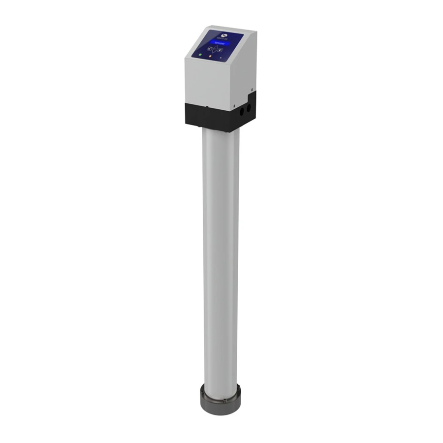
Page 6: Overview Of The Urspring
1.3 Overview of the UrSpring Page 6/50... -
Page 7: About This Manual
1.4 About this manual This manual describes how to safely use, install and maintain the Seccua UrSpring. Using the UrSpring is described first, because the end user will use the manual most oft ft f en fo fo f r this purpose. -
Page 8: Warranty
NOTICE By putting the UrSpring into operation, you automatically agree to the warranty conditions of Seccua GmbH. If you do not agree with the warranty conditions, do not operate the UrSpring and return it to your dealer. For a claim of the manufacturing warranty, a prior warranty registration is required via https://www.seccua.com/registration... -
Page 9: Using The Urspring
2. Using the UrSpring 2.1 User interface The UrSpring user interface on the control unit is shown in the image below. The Filter lifespan indicator shows the fo fo f llowing: Left ft f indicator is green (steady). The UrSpring is filtering correctly. -
Page 10: Using The Menu
2.2 Using the menu To go to a menu item use the buttons on the controller. Select the menu item with button. 2.3 Viewing controller measurements 2.3.1 Flow This indicates the flow of water through the filter in l/min (gpm). 2.3.2 Pressure drop (p-drop) This shows the current pressure difference between the feed water and filtered water in bar (psi). -
Page 11: Filter Life Left
NOTICE The maximum pressure difference may not exceed 2.5 bar (36.26 psi). A filter should reduce the pressure as little as possible. Therefore a high pressure difference is an indication that the filter is fouled (or the current water consumption exceeds the UrSpring capacity) and should be flushed (see ... -
Page 12: Enter The Serial Key (Sk)
Hot water ● Set automatic daily cleaning. See Daily flush ● Select automatic flushing when the filter is fo fo f uled. See Automatic flush when fouled ● Set the flush length to 5 sec. See 2.4.7 Set the flush length 2.4.1 Enter the serial key (SK) NOTICE The SK code is different for each type of filter. -
Page 13: Select The Time Format
2.4.6 Set the water temperature The water temperature setting is not available in the UrSpring Home.. NOTICE The water temperature influences the lifetime of the filter. The controller uses this setting to predict a precise lifetime. -
Page 14: Select To Delay Flush During Water Use
Therefore, do n ot activate this function when: ● the filtered water outlet is connected to a storage tank. ● the UrSpring is used in a hot water circulation device. To stop flush during water use: 1. Go to menu C hg. Flush mode? > F lush when Flow. -
Page 15: Automatic Flush When Fouled
NOTICE The UrSpring device can be set to perform an automatic cleaning of the filter, depending on its fouling. The UrSpring monitors the state of fouling of the filter using the pressure difference between feed water and filtered water, the flow during filtration and the temperature of the filtered water. -
Page 16: Preparation
NOTICE Make sure spilled water can not cause any damage. 1. Close the water in feed and filtered water lines. 2. Depressurize the UrSpring with a manual flush (see F lushing the filter module 3. Disconnect the power by removing the plug from the mains socket. -
Page 17: Place A New Filter Module
Note that a used filter module must be disposed of as described in Storage, handling and disposal 2.6.3 Place a new filter module To place a new filter module: 1. Prepare the new O-rings and filter module: see S TEP 4 Prepare the O-rings and filter module 2. -
Page 18: Installing The Urspring
● Abrasive particles in the feed water, such as metal or plastic debris, gravel or similar can damage the UrSpring filter. Therefo fo f re, a strainer with a maximum mesh size of 300µm needs to be placed upstream, to protect the filter of the UrSpring. -
Page 19: Additional Components To Be Included In The Water Lines
5 bar (72 psi). Caution, pressure of the public supply network can increase during the night! ● A shut off valve needs to be located upstream the UrSpring for installation and exchange of filter cartridges. ● If connected to a public water supply, a backflow preventer needs to be... - Page 20 ● Make sure there is sufficient space on the front side of the UrSpring to allow easy operation of the control unit and allow service and maintenance. ● Make sure that there is 20 cm (8") of space available below the UrSpring to allow filter replacement.
-
Page 21: Installation Steps
Please check the contents of the package immediately upon receipt for completeness and possible shipping damage. If the UrSpring or parts of the UrSpring have been damaged during transport, notify the transport company immediately. Transport damage to the UrSpring is not covered by warranty. -
Page 22: Step 2 Mount The Urspring
Q. UrSpring quick guide R. Inspection certificate STEP 2 Mount the UrSpring The UrSpring must be mounted to a firm wall as follows: 1. Attach the wall mounting plate to the control unit, using the supplied screws (M8x16). Page 22/50... - Page 23 2. Attach the control unit with the wall mounting plate to the wall. Use screws and plugs depending on your type of wall. Make sure the bottom of the control unit is at least 120 cm (47”) above the floor. Page 23/50...
-
Page 24: Step 3 Connect The Water Couplings
STEP 3 Connect the water couplings Your UrSpring package contains three John G uest quick connect couplings. These will be used in this instruction. If you decide to use other, custom couplings, only use couplings with a 22 mm (3/4") metric, non-tapered (parallel) external thread. - Page 25 2. Manually insert and turn the quick connect couplings into the control unit for the feed, filtered and drain water (hand tightened them, so the O-rings seal). NOTICE The couplings seal to the control unit with O - rings. The thread does not have to be sealed additionally.
-
Page 26: Step 4 Prepare The O-Rings And Filter Module
STEP 4 Prepare the O-rings and filter module 1. Remove the tape and protection caps from the top and bottom of the filter module. 2. Put on the sterile gloves. 3. Clean and disinfect the pipe tips that extend from the filter module using the alcohol pad. 4. - Page 27 7. Fit the second O-ring at the bottom of the control unit into the valve block. You can now take off ff f the gloves. Page 27/50...
-
Page 28: Step 5 Place The Filter Module
STEP 5 Place the filter module 1. Place the end cap on a flat surface and put the bottom of the filter in it. 2. Place the mounting clamps into the lower groove of the filter module. 3. Attach the clamps evenly using the four bolts (M8x50) until they touch the surface. (hand-tight, do not used pliers or additional tools other than the Allen key supplied). -
Page 29: Step 6 Connect The Power
7. Fasten the clamps evenly using the four bolts (M8x100), until they touch the surface. (hand-tight, do not used pliers or additional tools other than the Allen key supplied). STEP 6 Connect the power ● Do not connect if the plug or cable is damaged! ●... - Page 30 5. Connect the power plug into the mains socket. The welcome screen is shown on the user interf rf r ace. Hereaft ft f er, the controller prompts fo fo f r two settings: the serial key (SK) of the filter module and the controller language.
-
Page 31: Step 7 Rinse The Filter Membrane
UrSpring with water, replacing the contained air. 4. As soon as water starts flowing from the tap point; open the feed water shut off valve completely and flush the UrSpring rinse 3 to 5 minutes through one fully opened tap downstream, until water tastes fresh. -
Page 32: Maintenance
4. Maintenance Only qualified technicians are allowed to perf rf r o fo f rm maintenance on the UrSpring. Non-expert and insuff ff f icient maintenance will fo fo f rf rf r eit any warranty rights. 4.1 Maintenance schedule... -
Page 33: Maintenance Instructions
4.2 Maintenance instructions 4.2.1 Calibrating the pressure sensors Calibration of the pressure sensors may be required from time to time or when the UrSpring shows a sensor error (error code 109). Calibration adjusts the zero point of the pressure sensors to atmospheric pressure. During the calibration process, there may not be any pressure, flow or vibrations. -
Page 34: Exchanging The Pressure Sensors
4.2.3 Exchanging the pressure sensors When pressure reading on the controller gives unexpected results, check the pressure sensors by calibrating them (see 4 .2.1 Calibrating the pressure sensors When the controller display shows a sensor error, and you are sure that during the calibration there was no pressure, flow or vibration, then the pressure sensors (Art. -
Page 35: Exchanging The Solenoid Valve
4. Apply a tiny drop of threadlocker on the beginning of the thread of the new sensor. 5. Carefully insert the new pressure sensor into the valve block and turn it in by hand. 6. Tighten the sensor with the 22 mm torque wrench with 10 Nm. 7. - Page 36 3. Remove the fo fo f ur bolts (M4x20) from the existing valve. 4. Take off ff f the existing valve cover. 5. Remove the spring and membrane. 6. Remove the small O-rings. Page 36/50...
- Page 37 Place the new solenoid valve: 1. Clean the surf rf r ace of the valve block and the grooves in the membrane recess. 2. Clean the bore holes where the small O-rings were positioned. 3. Apply a little fo fo f od grade grease on the outer ring of the membrane recess. Page 37/50...
-
Page 38: Cleaning The Solenoid Valve
4. Apply a little food grade grease on the new small O-rings. 5. Put both O-rings on the valve block on the small bore holes. 6. Put the new membrane in its recess on the valve block with the brass taper downwards and the membrane with bypass upwards. -
Page 39: Exchanging The Flow Sensor
6. Apply grease and put all parts back as described in 4 .2.3 Exchanging the solenoid valve 4.2.6 Exchanging the flow sensor To exchange the flow sensor: 1. Remove the controller from the valve block as described in 4 .2.2 Removing the controller from the valve block... -
Page 40: Spare Parts
Spare part sets description Article no. UrSpring Controller-Set (controller + power supply cable) 12287 UrSpring Valve-block full equipped (full equipped valve block, 12293 with pressure sensors, flow, sensor and solenoid valve) UrSpring Wall-mounting-Set (Wall mounting plate + 4 x M8x16) 12288 Page 40/50... -
Page 41: Single Spare Parts
12289 adapters) UrSpring Top-clamp-Set (2 x clamps + 4 x M8x100) 12290 UrSpring O-Ring-Set complete (2 x 16x3 + 2 x 25x3 + 2 x 98x4 11301 + grease) SeccuMemPro 1000 (Filter fo fo f r all UrSpring types) 10545... -
Page 42: Troubleshooting
(11354)) UrSpring Power supply (cable + adapters) 10698 5. Troubleshooting If your UrSpring unit reports an error, the red LED on the controller will blink. 5.1 Error codes To view the error codes: 1. Go to menu View alerts. - Page 43 (Set the correct time Memory error. It might be that the power supply of the UrSpring was lost fo fo f r a longer time, make sure the power supply and socket work correctly. Contact your serv rv r ice technician.
-
Page 44: Support
5.2 Support For further support, please contact Support through our Service Desk. You find the required contact data under h ttps://www.seccua.com/service Page 44/50... -
Page 45: Specifications
6. Specifications 6.1 Dimensions 6.2 Operating data SI-units US-units Max. operating 5.0 bar 72 psi pressure Operating 4°C to 40°C 39°F to 104°F temperature Page 45/50... -
Page 46: Electrical Connection
6.3 Electrical connection The UrSpring is supplied with a power supply fo fo f r diff ff f erent power plugs and voltages.The power supply complies with EU Directive 2014/35/EC on Low Voltage Equipment. Country ry r Voltage Power (max.) -
Page 47: Using Pipe Couplings
7. Using pipe couplings 7.1 Using custom couplings If you use custom couplings to connect the water lines to the UrSpring, please note the following: ● The valve block of the control unit is made of plastic. Make sure that the internal thread of the valve block is not damaged during installation by the thread of the custom coupling used. - Page 48 To disconnect a pipe from the quick connect coupling: 1. Fully release the pressure from the UrSpring. 2. Press in the sleeve of the coupling. 3. Pull the pipe from the coupling. Page 48/50...
-
Page 49: Storage, Transport And Disposal
To place the UrSpring in a (temporary) storage: ● Disconnect the electricity and water supply. ● Remove water from the UrSpring. Water can become contaminated if it is not refreshed for a long time. ● Clean the external and internal surfaces of the UrSpring and accessories. -
Page 50: Transportation
8.2 Transportation When transporting the UrSpring: ● Make sure the temperature of the UrSpring [does not drop below 0 °C (32°F) or rise above 40 °C (104°F). ● Make sure the UrSpring is not subject to substantial vibrations or physical shocks. - Page 51 Data Sheet DS-1127 Tube Groove Details - Standard Imperial The information provided here relates to Stainless Steel and hard Tubing and to provide a groove beyond the collet teeth upon full insertion of tube. This groove will prevent the tube from slipping in most applications. The use of a tube cutter to produce the groove is a suggestion only and the groove produced by this method will depend on the model used.
- Page 52 Data Sheet DS-1127 Tube Groove Details - Standard Metric The information provided here relates to Stainless Steel and hard Tubing and to provide a groove beyond the collet teeth upon full insertion of tube. This groove will prevent the tube from slipping in most applications. The use of a tube cutter to produce the groove is a suggestion only and the groove produced by this method will depend on the model used.
Need help?
Do you have a question about the UrSpring and is the answer not in the manual?
Questions and answers