Table of Contents
Advertisement
Available languages
Available languages
Advertisement
Chapters
Table of Contents

Subscribe to Our Youtube Channel
Summary of Contents for FloTech FT204P
- Page 1 FloTech FT204P Programmable Retain / Overfill Onboard Monitor Dixon Bayco Dixon Bayco LTD. 4740T Interstate Dr. 2315 Bowman St. Cincinnati, OH 45246 Innisfil, ON L9S 3V6 513 874 8499 office 705 436 1125 office 513 874 8399 fax 705 436 6251 fax...
- Page 2 FloTech Programmable Retain / Overfill Monitor NOTES: 10464 REV C...
-
Page 3: Table Of Contents
FloTech Programmable Retain / Overfill Monitor Table of Contents Introduction ..................4 Monitor Features ................4 Monitor Indicators ................5 Monitor Connections ............... 5 Mounting Instructions ..............6 Monitor Housing ................. 6 Cable Installation Instructions ............7 Monitor Housing ................. 7 Wiring Instructions ................ -
Page 4: Introduction
FloTech FT203P Programmable Retain / Overfill Onboard Monitor. Monitor Features The FloTech FT203P Retain / Overfill Monitor have the following features: Operates on 12 VDC or 24 VDC systems. Monitors up to six overfill sensors. -
Page 5: Monitor Indicators
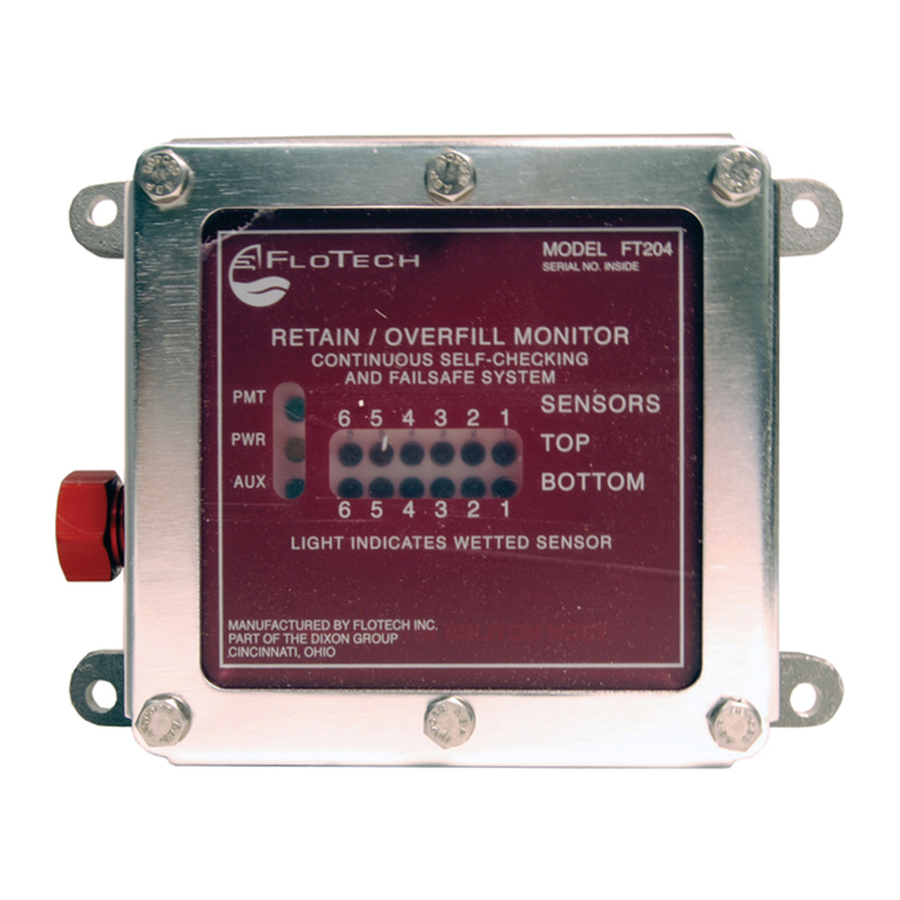
FloTech Programmable Retain / Overfill Monitor Monitor Indicators Refer to Fig. 1. PWR LED Yellow LED that indicates power is connected to the monitor. AUX LED Green LED indicates the Auxiliary input is permissive. PERMIT LED Green LED indicates to the rack the sensors are permissive. -
Page 6: Mounting Instructions
Fig. 2 Mounting Hole Pattern Detail Monitor Housing The FloTech model FT204 Retain / Overfill Monitor Housing is typically mounted on the trailer main frame rail, fitting storage box, or any flat surface within easy view of the bottom loading connections. -
Page 7: Cable Installation Instructions
Unused conduit openings in the sensor housings must have a ½ inch NPT pipe plug installed. Note that when using the FloTech FT390 Dual Socket Assembly, you only need to install one cable gland for the socket wiring. Fig. 3... -
Page 8: Wiring Instructions
FloTech recommends using FT401 seven conductor cable to wire the Onboard Monitor System. When stripping the rubber jacket from the cable, FloTech recommends using the FT9023 or equivalent Cable Stripper. This stripper has an adjustable cutting blade depth setting. The depth should be set to only cut through one-half to two-thirds of the outer jacket thickness. -
Page 9: Monitor Wiring Connections
FloTech Programmable Retain / Overfill Monitor 4. Fill a FloTech Butt Splice with Silicone RTV compound. Insert the twisted wires into the filled splice. Check to see that the bare wires are fully inserted into the splice and RTV. Make certain that NO bare wire is protruding from the splice. -
Page 10: Tb1 Power Connections
FloTech Programmable Retain / Overfill Monitor TB1 POWER Connections Refer to Fig. 4. FloTech recommends routing the trailer power through a weatherproof inline fuse holder containing a 1/2 amp fast blow fuse to the monitor. Optionally, a switch can be added in series with the fuse to the TB1 input. -
Page 11: Tb3 Float, Thermistor And Optic Socket Connections
FloTech Programmable Retain / Overfill Monitor TB3 Float, Thermistor, and Optic Socket Connections These connections and are wired to the appropriate socket(s) as dictated by the Loading Terminals in your area. At this time, FloTech offers the following sockets: FT300 API Optic Socket ... - Page 12 Optic Socket Connections Another Socket Option is to install the FloTech FT390 Dual Socket Assembly. This unit comes with the sockets pre-wired to a length of FloTech eleven conductor cable. Refer to Fig. 9 for wiring connections. 10464 REV C...
-
Page 13: Tb4 Aux Permit Connections
FloTech Programmable Retain / Overfill Monitor Fig. 9 FloTech FT390 Socket Connections TB4 AUX PERMIT Connections Refer to Fig. 6. In order for the FT203P Monitor to work properly, the AUX terminals must be connected together. This can be done either by placing a shorting jumper across the AUX terminals (factory installed) or by connecting the AUX terminals to a dry relay contact. -
Page 14: Tb5 Program Connections
FloTech Programmable Retain / Overfill Monitor TB5 RESET Connections Refer to Fig. 7 . The Reset/Timer terminals connect to a Normally Open push button switch. The primary function of this switch is to override wet Retain Sensors for „Splash Blending‟ product. When this button is pressed, the FT203P Monitor will issue a Permit signal to the Rack without regard to the Retain Sensors for up to 90 minutes. -
Page 15: Programming
FloTech Programmable Retain / Overfill Monitor Programming Overview Before the FloTech FT203P Monitor can be put into service, it must be programmed. This procedure informs the monitor which inputs have sensors attached. These inputs are then labeled as ACTIVE sensors. The remaining inputs that do NOT have sensors attached are labeled as INACTIVE inputs. -
Page 16: Operation
FloTech Programmable Retain / Overfill Monitor 4) Move SW1 to “PRGM” on Program Module. 5) Turn on the power. The sensor LEDs will sequentially flash through the power up test pattern. 6) The sensor LEDs will light up the last valid configuration. -
Page 17: Troubleshooting
FloTech Programmable Retain / Overfill Monitor All the sensor inputs that have been programmed as inactive “no sensors” see no signals. The AUX input has a jumper or made through an external set of contacts. A PERMIT signal will NOT be issued if: ... - Page 18 This means that the monitor is not programmed. 1. Go to the PROGRAMMING section of this manual and program the monitor. 2. If the monitor fails to program, call FloTech for Technical Service. System will not load and one or more RED sensor LEDs are lit on inactive sensor inputs: Follow these instructions for top or bottom sensors.
- Page 19 Example: LED TOP #3 top stays lit after the sensor wires are switched. Replace the onboard monitor chassis with a FloTech model FT203P. 5. If the lit sensor LED moves to the new switched compartment, the problem is with the sensor or wiring.
- Page 20 To troubleshoot this condition, use the FloTech FT520 Optic System Tester or a Scully Universal Tester 1. Check the system by connecting a FloTech FT520 Optic System Tester or a Scully Universal Tester to the Socket output. Check for a good light on all compartments.
-
Page 21: Technical Support Hotline
2. If the switch tests OK then replace the monitor. Technical Support Hotline (877) 582-3569 Contact the FloTech Technical Support Hotline for help: Troubleshooting overfill systems. Verifying defective components To request an RGA to return FloTech products for warranty inspection. 10464 REV C... - Page 22 Mode d’emploi pour Moniteur intégré programmable FT204 FloTech pour capteur de fond/anti- débordement Pour vente & service contactez Dixon Bayco Dixon Bayco LTD. Canada: E-U: 4740T Interstate Dr. 2315 Bowman St. Dixon Group Canada Limited Dixon Bayco USA Cincinnati, OH 45246...
- Page 23 Moniteur programmable FloTech de fond/anti-déversement Table des matières Introduction ................3 Caractéristiques des moniteurs ..........3 Indicateurs de moniteurs ............4 Connexions du moniteur ............4 Instructions d’installation ............5 Boitier du moniteur ..............5 Instructions pour l'installation des câbles ........6 Boitier du moniteur ..............
-
Page 24: Introduction
FloTech de fond/anti-déversement FT203P. Caractéristiques des moniteurs Les moniteurs de fond/anti-déversement FloTech FT203P ont les caractéristiques suivantes : Fonctionne sur un système 12VDC ou 24VDC. -
Page 25: Indicateurs De Moniteurs
Moniteur programmable FloTech de fond/anti-déversement Indicateurs du moniteur Faites référence à la Fig. 1. PWR LED L’indicateur LED jaune indique que l’alimentation électrique est connectée au moniteur. AUX LED L’indicateur LED vert indique que le signal d’entrée Auxiliaire donne une permission. -
Page 26: Instructions D'installation
Moniteur programmable FloTech de fond/anti-déversement Instructions d’installation Fig. 2 Configuration des trous de montages Boitier du moniteur Le modèle FloTech FT204 de fond / anti-déversement du boitier du moniteur est généralement installé sur le longeron principal de la citerne, sur la boite de rangement de montage ou n’importe quelle surface plate qui permet de voir la connexion... -
Page 27: Instructions Pour L'installation Des Câbles
Nous vous recommandons d’utiliser le FT401 à 7 câbles conducteurs lorsque vous installez un nouveau système. Ce câble FloTech est conçu pour être résistant à l’huile, UV et à l’abrasion. Nous intégrons un fil de cuivre en torons étamé et plaqué... -
Page 28: Instructions De Câblage
équipement. Dénuder les câbles FloTech vous recommande d’utiliser un FT401 à 7 câbles conducteurs pour le câblage du système du moniteur intégré. Lorsque vous dénudez les câbles, FloTech vous recommande d’utiliser un FT9023 ou une pince à... - Page 29 Moniteur programmable FloTech de fond/anti-déversement Les connexion bout-à-bout FloTech vous recommande d’utiliser un FT9022 ou un outil de sertissage semblable pour sécuriser les connexions bout-à-bout. Suivez ces étapes pour sécuriser chaque connexion: 1. Suivez les instructions pour dénuder les câbles dans le paragraphe ci-dessus pour exposer le conducteur individuel du fil.
-
Page 30: Connexions Du Câblage Sur Moniteur
Connexion de l’alimentation électrique TB1 Faites référence à la Fig. 4. FloTech vous recommande de diriger l’alimentation électrique de la remorque à travers un support à l’épreuve des éléments pour fusible en ligne de ½ A vers moniteur. -
Page 31: Fond
Connexion de l’alimentation du moniteur Connexions TB2 pour capteur supérieur et capteur de fond. FloTech vous recommande d’installer le capteur au moniteur FT203P avec un câble FT401 à 7 brins en utilisant les couleurs comme indiqué sur la Fig.5. Le diagramme complet du câblage est représenté à l’arrière de cette brochure. - Page 32 Moniteur programmable FloTech de fond/anti-déversement Prise flottante API FT302 Contact optique avec entaille J de thermistance FT303 Prise Canadienne/ de thermistance Euro FT304 Prise de thermistance modèle FT305 J560 Prise optique modèle FT306 J560 Prise optique et de thermistance API double FT390 Faites référence au Figures de 6 à...
- Page 33 Connexions des prises de thermistances Fig. 8 Connexion des prises optiques L’installation du FT390 FloTech à prise double est aussi une autre option. Cette pièce vient avec une prise filetée d’avance avec une longueur d’un câble FloTech à 11 conducteurs. Faites référence à...
-
Page 34: Connexion Aux, Permit Tb4 (Permission)
Moniteur programmable FloTech de fond/anti-déversement Connexion AUX, PERMIT du TB4 Faites référence à la Fig. 6. De façon que le moniteur FT203P fonctionne correctement, les terminaux AUX doivent être connectés ensemble. Le moniteur vient de la manufacture avec une bretelle (jumper) installé, qui connecte les terminaux AUX ensemble. -
Page 35: Remise À Zéro De La Connexion Tb5
Moniteur programmable FloTech de fond/anti-déversement Remise à zéro de la connexion TB5 Faites référence à la Fig. 7. Le terminal reset/timer se connecte normalement sur un interrupteur bouton-poussoir qui est normalement ouvert. La fonction primaire de cet interrupteur est d’outrepassé le capteur de fond mouillé durant le mélange du produit dans la citerne. -
Page 36: Programmation
Moniteur programmable FloTech de fond/anti-déversement La Programmation Vue d’ensemble Avant que le moniteur FT203P FloTech soit mit en service il doit être programmé. Cette procédure informe le moniteur quelle entrée à un capteur connecté. Ces entrées sont étiquetées comme capteur actif. Le reste des entrées qui n’ont pas de capteurs connectés sont des entrées inactives. -
Page 37: Fonctionnement Normal
Moniteur programmable FloTech de fond/anti-déversement Position du module de programmation 4) Changer le SW1 pour le “PGM” sur le module de programme. 5) Allumez l’alimentation électrique. L’indicateur LED du capteur clignotera séquentiellement pendant l’essai sous tension. 6) L’indicateur LED du capteur allumera la configuration valide la plus récente. -
Page 38: Problème De Fonctionnement
Moniteur programmable FloTech de fond/anti-déversement haut ensuite du #1 au #6 du bas. Une fois cette séquence terminé, le moniteur test toutes les entrées des capteurs. Le signal PERMIT sera allumé si: Le moniteur est connecté correctement. Le moniteur reçoit un signal d’un capteur sec. - Page 39 Moniteur programmable FloTech de fond/anti-déversement Si le voltage du TB1 est correct remplacez le moniteur. NOTE: N’utilisez pas un chargeur de batterie pour l’alimentation électrique de la citerne. Un chargeur de batterie ne transmet pas un voltage DC stable et pur et ceci endommagera le moniteur intégré.
- Page 40 1. Allez dans la section de programmation de ce manuel et programmez le moniteur. 2. Si la programmation du moniteur ne fonctionne pas, appelez FloTech pour le support technique au 877-582- 3569. Le système ne permet pas un chargement et un ou plus indicateurs LED sont allumés pour les entrées...
- Page 41 Moniteur programmable FloTech de fond/anti-déversement Par exemple: Si l’indicateur LED du haut #3 est allumé, retirez le fil hors du terminal T3 (jaune). 3. Choisissez un compartiment où l’indicateur LED n’est pas allumé et échangez-le avec le fil en question. Par exemple: échangez le fil du haut #3 qui ne fonctionne...
- Page 42 Moniteur programmable FloTech de fond/anti-déversement Le système permet pas un chargement, les indicateurs LED vert AUX, vert PERMIT ne s’allument pas, L’ indicateurs d’alimentation électrique est allumé et les indicateurs rouges de capteur LED ne sont pas allumés. 1. Vérifiez l’entrée AUX TB4.
- Page 43 FT520 FloTech d’essai ou un testeur universel Scully. 1. Vérifiez le système en connectant le testeur pour système optique FT520 Flotech ou un testeur universel Scully sur la prise. Vérifiez les indicateurs de chaque compartiment.
-
Page 44: Pour Support Technique
Pour support technique (877) 582-3569 Pour assistance contactez le support technique FloTech: Problèmes avec les systèmes anti-débordement. Vérifiez les composants défectueux Si vous voulez retourner un produit FloTech pour une inspection pour la garantie. 10464(fr) REV C...
Need help?
Do you have a question about the FT204P and is the answer not in the manual?
Questions and answers