
Summary of Contents for Fred’s Lab TOORO
- Page 1 T ¨ O ¨ OR ¨ O module User and service Manual Revision 1.0 EN - 24/03/2021 for Firmware V1.20 - 08/03/2021 Fr ´ e d ´ e ric Meslin / Fred’s Lab March 29, 2021...
- Page 2 Introduction Thank you very much for purchasing the T¨ o ¨ o r¨ o ! This is the second multitimbral synthesizer from Fred’s Lab and our best attempt at hybrid polyphonic synthesis. By carefully blending analog and digital technologies, mixing 1970’s and 2020’s electronics and pouring it in a compact and rugged package, the T¨...
- Page 3 Warranty Fred’s Lab warranty this product free of defects 3 years from its date of purchase. This warranty covers product from manufacturing defects, when the product is used ob- serving normal operating conditions. However, the warranty does not cover: ˆ Normal product wear-out ˆ...
- Page 4 The T¨ o ¨ o r¨ o ! used in conjunction with headphones and speaker systems can produce very loud sounds in a wide range of frequencies. Human hearing is very sensitive and can be damaged quickly. So watch out your hears and those of your audience!
-
Page 5: Table Of Contents
Contents Contents Contents 1 Presentation 1.1 What is MIDI? ........1.2 Remarks on polyphony . - Page 6 Contents Contents 6.3.8 Sync ........22 6.4 Extra .
- Page 7 Contents Contents 6.11.9 Example 1: Applying LFO 1 Modulation on Osc 1 Pitch ..37 6.11.10 Example 2: Applying Pitch Modulation on Amplifier Pan ..37 7 Multi Parameters 7.1 Overview .
- Page 8 Contents Contents 11.2 System Real Time Messages ......46 11.2.1 Clock Start ....... . 46 11.2.2 Clock Continue .
-
Page 9: Presentation
2 REQUIREMENTS 1 Presentation The T¨ o ¨ o r¨ o is a 6-voice polyphonic, 4-part multi-timbral, hybrid ”digilog” MIDI sound module. ˆ Polyphonic means it can play several notes at the same time. ˆ Multi-timbral means it can play several instruments at the same time. ˆ... -
Page 10: A Midi Controller
2.2 A MIDI controller 2 REQUIREMENTS 2.2 A MIDI controller can be any master keyboard, wind controller, surface... that sends MIDI notes. You can also attach the instrument to a hardware or software MIDI sequencer. It can run on a computer, a laptop or a tablet/smartphone. -
Page 11: Instrument Setup
3 INSTRUMENT SETUP 3 Instrument Setup Step 1: Audio Connect the T¨ o ¨ o r¨ o line-level outputs (left & right) to your audio system inputs using two 6.35mm unbalanced jacks. Step 2: MIDI Connect the T¨ o ¨ o r¨ o MIDI DIN input (MIDI IN) to your MIDI compatible controller or sequencer/computer using a MIDI DIN cable. -
Page 12: Instrument Operation
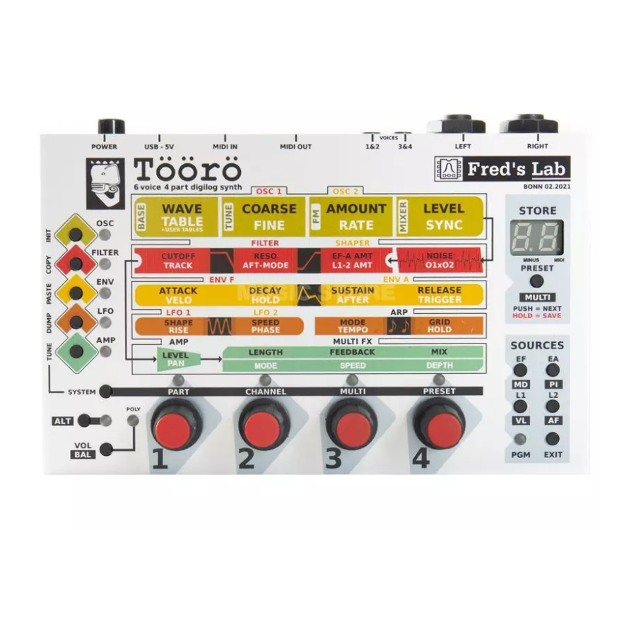
4 INSTRUMENT OPERATION 4 Instrument Operation Once the instrument is properly installed and you can hear some sounds when playing notes, let’s have a good look at its panel: 4.1 Connectors A USB - 5V This is the USB-B connector for both power and MIDI over USB function. It must be attached to a source to power up the T¨... -
Page 13: Controls & Indicators
4.2 Controls & Indicators 4 INSTRUMENT OPERATION F LEFT & RIGHT These are the main outputs to be connected to a mixing desk, audio interface of power speaker system. 4.2 Controls & Indicators 1 Power Switch Switches the power on or off. 2 Module Buttons &... -
Page 14: Editing Parameters
4.3 Editing Parameters 4 INSTRUMENT OPERATION 10 Sources Buttons Enters matrix programming mode and selects the source to modulate a sound parameter. If alternate mode is enabled via the ALT button, a second set of sources can be selected and assigned. 11 PRESET/MULTI Button Loads and saves presets and multis. -
Page 15: Preset & Multi Management
5 PRESET & MULTI MANAGEMENT 5 Preset & Multi Management The T¨ o ¨ o r¨ o is a multi-timbral device that can store 100 presets and 10 multis. All memory locations can be overwritten by the user, so the factory patches can be overwritten. An important concept to understand is that there is no separation between preset and multi mode, the T¨... -
Page 16: Saving A Preset
5.4 Saving a Preset 5 PRESET & MULTI MANAGEMENT ˆ Press and hold the SYSTEM button. Then use the fourth parameter encoder labelled PRESET to increment or decrement the preset number. Preset selection 0..99 5.4 Saving a Preset 5.4.1 Overwriting the Current Preset To save an edited preset onto the current memory location, press and hold down the PRESET button until the display starts to blink. -
Page 17: Selecting A Multi
5.8 Selecting a Multi 5 PRESET & MULTI MANAGEMENT To dump a preset over USB MIDI, press and hold the SYSTEM button and then press the Module button labelled LFO. This button also has a secondary vertical label DUMP left to it. You can dump back a preset from your computer or sequencer at any time. -
Page 18: Copying Multis
5.10 Copying Multis 5 PRESET & MULTI MANAGEMENT 5.10 Copying Multis Multis can be copied to another location via copy & paste in a similar way as described above under Saving a Multi to a Different Memory Location. 5.11 Initializing a Multi To initialize a multi, while in alternate mode, press and hold the SYSTEM button and then press the Module button labelled OSC. -
Page 19: Preset Parameters
6 PRESET PARAMETERS 6 Preset Parameters 6.1 Overview T¨ o ¨ o r¨ o overall preset structure Notes: ˆ The preset name is only accessible by Sysex messages. ˆ The Tune and Band Range parameters are only accessible via Sysex and MIDI CC messages. -
Page 20: Oscillators
6.3 Oscillators 6 PRESET PARAMETERS 6.3 Oscillators The T¨ o ¨ o r¨ o has two identical wavetable oscillators that build the heart of the sound engine. Each oscillator generates a blended waveform that is determined by the content of the selected wavetable. In addition, FM modulation and auto-sync is possible within a single oscillator to produce alterations of the harmonic content. -
Page 21: Coarse Tune
6.3 Oscillators 6 PRESET PARAMETERS There are 8 factory wavetables and one user wavetable to choose from: Basic Sawtooth Square Triangle Sine Blue Noise Brown Noise Metal Over- Bright tones Bell-like Double Saw Double Square Organ Full Prime Numbers Formant A Formant E Formant O Formants... -
Page 22: Fm Amount
6.3 Oscillators 6 PRESET PARAMETERS 6.3.5 FM Amount The FM feature offers a phase modulation that uses the selected wave as carrier and a sine wave as modulator. This parameter sets the amount of modulation that is applied to the carrier. 6.3.6 FM Rate Sets the frequency of the modulator sine wave for the phase modulation. -
Page 23: Extra
6.4 Extra 6 PRESET PARAMETERS 6.4 Extra This module offers two additional signal sources that can be mixed with the oscillators before being routed to the shaper. To access the extra parameters, press the FILTER module button. If you press the button more than once, the selection will cycle between filter and shaper. -
Page 24: Filter
6.5 Filter 6 PRESET PARAMETERS 6.5 Filter This module is one of the main sound-shaping components of the T¨ o ¨ o r¨ o and is built upon a discret analog design, the FL A847 optocoupled resonant filter. It offers a 12db/octave low-pass with a unique sound. -
Page 25: Pitch Tracking
6.5 Filter 6 PRESET PARAMETERS 6.5.5 Pitch Tracking This parameter allows the cutoff frequency to follow the pitch of the played notes. The effective pitch is calculated from the note number but also includes any modulation via the pitch wheel. The reference note number where modulation is unaffected is 36. The range of this parameter reaches from -200% to +200%. -
Page 26: Shaper
6.6 Shaper 6 PRESET PARAMETERS 6.6 Shaper The shaper is a module located right after the mixer stage and allows additional processing before the signal is routed to the analog filter. It offers a multimode filter that can be configured as low-pass, band-pass or high-pass. To access the shaper parameters, press the FILTER module button. -
Page 27: Pitch Tracking
6.6 Shaper 6 PRESET PARAMETERS 6.6.5 Pitch Tracking This parameter allows the cutoff frequency to follow the pitch of the played notes. The effective pitch is calculated from the note number but also includes any modulation via the pitch wheel. The reference note number where modulation is unaffected is 36. The range of this parameter reaches from -200% to +200%. -
Page 28: Lfos
6.7 LFOs 6 PRESET PARAMETERS 6.7 LFOs The T¨ o ¨ o r¨ o has 2 independent LFOs that can be used for various modulation purposes. To access the LFO parameters, press the LFO module button. If you press the button more than once, the selection will cycle between LFO 1 and LFO 2. -
Page 29: Rise
6.7 LFOs 6 PRESET PARAMETERS 6.7.3 Rise Sometimes it’s not desirable to have the LFO at its full modulation after a note is played, but gradually fading it in. This is what the rise parameter does. It allows you to ramp up the modulation depth slowly up to 18 seconds. -
Page 30: Envelopes
6.8 Envelopes 6 PRESET PARAMETERS 6.8 Envelopes The T¨ o ¨ o r¨ o has 2 independent envelopes that are designated for filter and amplifier mod- ulation in first place, but can also be used for other modulation purposes. In addition to the standard ADSR-type envelopes, the T¨... -
Page 31: Release Time
6.8 Envelopes 6 PRESET PARAMETERS 6.8.4 Release Time Sets the time to fall from the sustain level to 0 after the trigger is released. 6.8.5 Velocity Amount This parameter allows to control the overall modulation amount of the envelope via the note velocity. -
Page 32: Amplifier
6.9 Amplifier 6 PRESET PARAMETERS 6.9 Amplifier The amplifier is the last module in the chain before the signal is routed to the parts mixer. It allows you to set the overall preset volume and panorama position. Press the module button AMP to access the parameters of the amplifier. The display will show the selected module briefly: Amplifier In normal mode, the Level can be edited via the first encoder. -
Page 33: Arpeggiator
6.10 Arpeggiator 6 PRESET PARAMETERS 6.10 Arpeggiator The arpeggiator is a module that allows the creation of melodic patterns from chords or single notes. Press the module button LFO to access the parameters of the arpeggiator. If you press the button more than once, the selection will cycle between LFO 1 and LFO 2. -
Page 34: Tempo
6.10 Arpeggiator 6 PRESET PARAMETERS Display value Note value 1/2 triplet 1/4 triplet 1/8 triplet 1/16 1/32 1/32 triplet 1/64 triplet The gate length of the notes is always equivalent to 50% of the note value. Note: to modify the perceived gate length, make use of the envelope hold and decay parameters. -
Page 35: Modulation Matrix
6.11 Modulation Matrix 6 PRESET PARAMETERS 6.11 Modulation Matrix The T¨ o ¨ o r¨ o offers a modulation matrix with 8 sources. Each source can only modulate one destination. To assign the modulation sources to the different destinations, the matrix programming mode has to be entered. -
Page 36: Modulation Sources
6.11 Modulation Matrix 6 PRESET PARAMETERS 6.11.6 Modulation Sources The following modulation sources can be used: Env F (Filter envelope) Env A (Amplifier envelope) LFO 1 LFO 2 Mod wheel Pitch (note number & pitch wheel) Note velocity Aftertouch 6.11.7 Modulation Destinations The following parameters can be used as modulation destinations: Module Parameters... -
Page 37: Example 1: Applying Lfo 1 Modulation On Osc 1 Pitch
6.11 Modulation Matrix 6 PRESET PARAMETERS Furthermore, there is a default assignment for vibrato via mod wheel. Whenever the modulation amount of the mod wheel is set to 0 or modulation is disabled, a default modulation of LFO 2 to master pitch is applied and its intensity is controlled by the mod wheel. -
Page 38: Multi Parameters
7 MULTI PARAMETERS 7 Multi Parameters 7.1 Overview T¨ o ¨ o r¨ o overall multi structure Note: The multi name is only accessible by Sysex messages. 7.2 Parts Mixer The parts mixer allows to control the volume and balance of all parts. The four encoders correspond to the part number. -
Page 39: Multi Fx
7.3 Multi FX 7 MULTI PARAMETERS 7.3 Multi FX The T¨ o ¨ o r¨ o offers time-domain effects that are based on the repetition of the original signal at different intervals. The delay time of each effect can be modulated by an internal LFO. -
Page 40: Speed
7.3 Multi FX 7 MULTI PARAMETERS 7.3.5 Speed Sets the speed of the modulation that is applied to the delay time. It covers a range from 16s to 6Hz. 7.3.6 Depth Sets the amount of modulation that is applied to the delay time. -
Page 41: Filter Tuning
Important: Failing to observe the update procedure may simply brick your device! Therefore, please proceed carefully. To update your T¨ o ¨ o r¨ o instrument to the latest firmware revision, please refer to the appropriate update documentation and read the following tutorials at: https://fredslab.net/en/tooro-module.php... -
Page 42: Specifications
10 SPECIFICATIONS 10 Specifications Here you will find all technical data concerning the T¨ o ¨ o r¨ o . 10.1 Sound Engine 10.1.1 General ˆ Number of parts: 4 ˆ Maximal polyphony: 6 voices ˆ MIDI channel selection, overall volume and panning settings per part 10.1.2 Oscillators Two 12bit digital oscillators with: ˆ... -
Page 43: Dca
10.2 Memory 10 SPECIFICATIONS 10.1.8 DCA Digitally controlled attenuator with volume and panning control. 10.1.9 Multi FX Effect types: ˆ Mono modulated delay ˆ Stereo chorus / flanger ˆ Stereo modulated line 10.2 Memory ˆ 100 user presets ˆ 10 user multis 10.3 Line Outputs ˆ... -
Page 44: User Interface
10.8 User Interface 10 SPECIFICATIONS 10.8 User Interface ˆ 4 encoders ˆ 14 tactile switches ˆ Dual digit 7-segment hexadecimal display ˆ 12 leds ˆ 1 power switch 10.9 Dimensions & Weight ˆ 160mm x 100mm x 60mm (unit) ˆ 350 grams (unit) 10.10 Mechanics ˆ... -
Page 45: Midi Implementation
11 MIDI IMPLEMENTATION 11 MIDI Implementation 11.1 Channel Voice Messages Channel Voice Messages are used to send basic music events to one specific channel or part. They consists in 3 bytes: the status byte, followed by two data bytes. Here follows the list of supported messages. -
Page 46: Program Change
11.2 System Real Time Messages 11 MIDI IMPLEMENTATION Since MIDI CCs can only transmit 7 bit values, values transmitted are internally interpolated and smoothed. 11.1.5 Program Change Selects the current preset. Byte: 0 Data: 0xCc preset = MIDI channel (0 - 15) preset = preset number (0 - 99) 11.1.6 Channel Aftertouch Controls the pressure level of the given channel (= part) notes. -
Page 47: Clock Stop
11.2 System Real Time Messages 11 MIDI IMPLEMENTATION 11.2.3 Clock Stop Stop all parts arpeggiator. Byte: 0 Data: 0xFC 11.2.4 Clock Tick Synchronizes the MIDI master clock of the sound module. A tick corresponds to 1/24th of a quarter note. Byte: 0 Data: 0xF8 11.2.5 Active Sensing... -
Page 48: Midi Cc Assignments
11.3 MIDI CC Assignments 11 MIDI IMPLEMENTATION 11.3 MIDI CC Assignments Controller Change Messages are used to alter sound parameters of a given channel. They allow more musical expressivity by adjusting the sound character while playing or allow the editing of the part parameters from an extended/remote MIDI interface or a computer software (sequencer or preset editor). - Page 49 11.3 MIDI CC Assignments 11 MIDI IMPLEMENTATION Section Parameter CC Number Preset Filter Resonance Filter Cutoff Filter Env F Amount Filter Track Filter After Filter LFO 1 Amount Shaper Cutoff Shaper Resonance Shaper Env A Amount Shaper Track Shaper Mode Shaper LFO 2 Amount LFO 1 Shape LFO 1 Speed...
-
Page 50: Sysex Implementation
12 SYSEX IMPLEMENTATION 12 Sysex Implementation Sysex or System Exclusive Messages are lengthier MIDI messages used to transfer, save and load preset and multi parameters. Two types of messages exist: requests and dumps. Requests are sent to the music instrument to ask for the dump of a specific preset or multi. -
Page 51: Preset Dump
12.2 Dumps 12 SYSEX IMPLEMENTATION Index Length Description Preset ID Part 1 Preset ID Part 2 Preset ID Part 3 Preset ID Part 4 MIDI Channel Part 1 MIDI Channel Part 2 MIDI Channel Part 3 MIDI Channel Part 4 Volume Part 1 Volume Part 2 Volume Part 3... - Page 52 12.2 Dumps 12 SYSEX IMPLEMENTATION Index Length Description Osc 1 Wave Osc 1 Coarse Osc 1 FM Amount Osc 1 Level Osc 1 Table Osc 1 Fine Osc 1 FM Rate Osc 1 Sync Osc 2 Wave Osc 2 Coarse Osc 2 FM Amount Osc 2 Level Osc 2 Table...
- Page 53 12.2 Dumps 12 SYSEX IMPLEMENTATION Index Length Description LFO 1 Shape LFO 1 Speed LFO 1 Rise LFO 1 Phase LFO 2 Shape LFO 2 Speed LFO 2 Rise LFO 2 Phase Arp Mode Arp Grid Arp Tempo Arp Hold Amp Level Amp Pan Env F Amount...
-
Page 54: Data Packing
12.2 Dumps 12 SYSEX IMPLEMENTATION 12.2.3 Data Packing Sysex payload data is packed because of the 7-bit restriction of the MIDI format. Byte Description byte 0, lowest 7 bits byte 1, lowest 7 bits byte 2, lowest 7 bits byte 3, lowest 7 bits tops, top 7th bits of the 4 preceeding bytes byte 4, lowest 7 bits byte 5, lowest 7 bits... -
Page 55: Schematics
13 SCHEMATICS 13 Schematics To minimize electronic waste and ensure long product life, Fred’s Lab is willing to pro- vide all technical documents needed to repair his products. The following schematics are provided ”as is” with no warranty of any kind. Any modification made to a Fred’s Lab instrument immediately voids the included 3-year product warranty. - Page 56 13 SCHEMATICS...
- Page 57 13 SCHEMATICS...
- Page 58 13 SCHEMATICS...
- Page 59 13 SCHEMATICS...
- Page 60 13 SCHEMATICS...
- Page 61 13 SCHEMATICS...
- Page 62 13 SCHEMATICS...
- Page 63 13 SCHEMATICS...
- Page 64 13 SCHEMATICS...
-
Page 65: Norms
14 NORMS 14 Norms 14.1 Europe: CE CE DECLARATION OF CONFORMITY 1. Product unique identification: T¨ o ¨ o r¨ o analog and digital sound module Belonging to the category ”multimedia electronic equipment” 2. Address of the manufacturer and his authorized representative: Fr´... -
Page 66: Canada: Interference Regulation
14.2 Canada: Interference Regulation 14 NORMS 14.2 Canada: Interference Regulation This device does not exceed the Class B limits for radio noise emissions from digital apparatus set out in the radio interference regulation of the Canadian Department of Communications. Cet ´ e quipement n’´ e met pas de bruits radiofr´ e quence d´ e passant les limites applicables aux appareils num´...
Need help?
Do you have a question about the TOORO and is the answer not in the manual?
Questions and answers