Table of Contents
Advertisement
Quick Links
INSTALLATION MANUAL
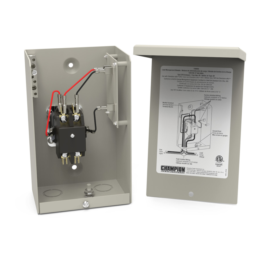
MODEL #100868
LOAD MANAgEMENT MODULE
REGISTER YOUR PRODUCT ONLINE
at championpowerequipment.com
or visit championpowerequipment.com
SAVE THESE INSTRUCTIONS. This manual contains important safety precautions which should be
read and understood before operating the product. Failure to do so could result in serious injury. This
manual should remain with the product.
Specifications, descriptions and illustrations in this manual are as accurate as known at the time of
publication, but are subject to change without notice.
REV 20201029
Champion Power Equipment, Inc., Santa Fe Springs, CA USA
Advertisement
Table of Contents

Summary of Contents for Champion Power Equipment 100868
- Page 1 Specifications, descriptions and illustrations in this manual are as accurate as known at the time of publication, but are subject to change without notice. REV 20201029 Champion Power Equipment, Inc., Santa Fe Springs, CA USA...
-
Page 2: Table Of Contents
100868 - LOAD MANAgEMENT MODULE TAbLE Of CONTENTS TAbLE Of CONTENTS Introduction ............Safety Definitions . -
Page 3: Introduction
100868 - LOAD MANAgEMENT MODULE INTRODUCTION INTRODUCTION SAfETY DEfINITIONS Congratulations on your purchase of a Champion The purpose of safety symbols is to attract your Power Equipment (CPE) product. CPE designs, attention to possible dangers. The safety symbols, builds, and supports all of our products to strict and their explanations, deserve your careful specifications and guidelines. -
Page 4: Important Safety Instructions
100868 - LOAD MANAgEMENT MODULE IMpORTANT SAfETY INSTRUCTIONS IMpORTANT SAfETY The warnings in this manual, tags and decals affixed to the unit are, therefore, not all-inclusive. If using INSTRUCTIONS a procedure, work method or operating technique the manufacturer does not specifically recommend follow all codes to ensure safety for personnel. - Page 5 100868 - LOAD MANAgEMENT MODULE IMpORTANT SAfETY INSTRUCTIONS WARNINg Be certain that the power from the utility is turned off and all backup sources are locked out before starting this procedure. Failure to do so could result in serious injury or death.
-
Page 6: Safety And Dataplate Labels
Read Operator’s Manual. To reduce the risk of injury, user must to Champion Power Equipment. The contents are confidential and privileged and shall not be disclosed to or used by or for ut the explicit consent of Champion Power Equipment. -
Page 7: Controls And Features
100868 - LOAD MANAgEMENT MODULE CONTROLS AND fEATURES CONTROLS AND fEATURES Read this installation manual before installing your LMM. Familiarize yourself with the location and function of the controls and features. Save this manual for future reference. The remote LMM turns power on and off to the load by using a Power Line Carrier (PLC) signal. The unit is capable of controlling resistive loads up to 50 Amps when wired into the load circuit. -
Page 8: Electrical Installation Diagram
100868 - LOAD MANAgEMENT MODULE CONTROLS AND fEATURES Electrical Installation Diagram UTILITY GENERATOR METER AIR CONDITIONER HOME PANEL LOAD MANAGEMENT MODULE... -
Page 9: Installation
100868 - LOAD MANAgEMENT MODULE INSTALLATION INSTALLATION Unpacking Carefully unpack the LMM. Inspect closely for any damage that might have occurred during shipment. Check that all packing material is completely removed from the LMM prior to installation. Handle LMM carefully when installing. - Page 10 100868 - LOAD MANAgEMENT MODULE INSTALLATION 3. Connect the L1 and L2 Line to the top of the 5. Connect the ground to the ground terminal. contactor relay (LINE connections). 6. Max. Torque Line, Load Terminals and Ground 4. Connect the L1 and L2 lines to the bottom of Terminal to 25 in.
-
Page 11: Connecting The Lmm To The Ats
100868 - LOAD MANAgEMENT MODULE INSTALLATION Setting DIp Switches Replace the cover. The DIP Switches set parameters of the controller. There are only 3 DIP switches on the LMM. These are the designated “ON” or “OFF” position settings for the DIP switches;... -
Page 12: Teaching System
100868 - LOAD MANAgEMENT MODULE TEACHINg SYSTEM Repeat this process if LMM units are added or removed from the system. 1 2 3 4 5 6 7 8 9 10 11 12 1 2 3 4 5 6 7 8 9 10 11 12... -
Page 13: Specifications
100868 - LOAD MANAgEMENT MODULE SpECIfICATIONS SpECIfICATIONS Unit Enclosure type...............NEMA 3R indoor/outdoor Amperage ..................50A resistive Nominal Voltage ..................240VAC Height..................8.2 in. (208 mm) Width..................5.2 in. (133 mm) Depth ..................3.8 in. (97 mm) Torque Neutral Bar .......... - Page 14 Champion Power Equipment disclaims any obligation to cover any loss of time, use of this product, freight, two years (parts and labor) from the original date of...
Need help?
Do you have a question about the 100868 and is the answer not in the manual?
Questions and answers