Advertisement
INSTRUCTION MANUAL
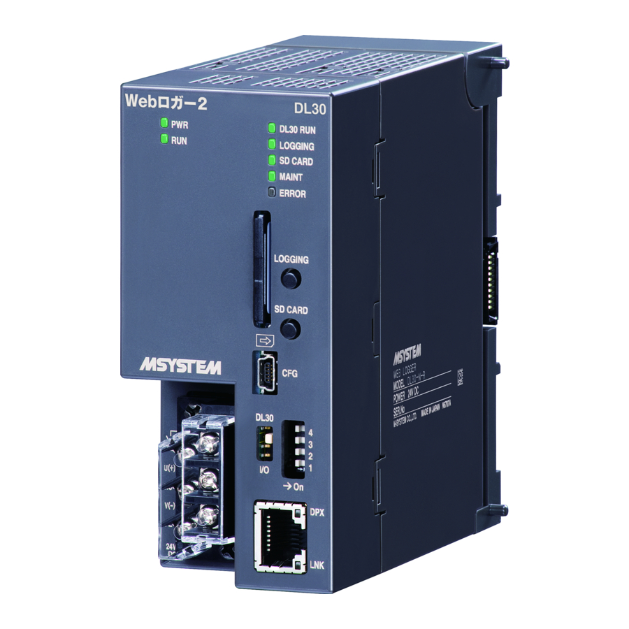
WEB-ENABLED REMOTE TERMINAL UNIT
BEFORE USE ....
Thank you for choosing M-System. Before use, please check
contents of the package you received as outlined below.
If you have any problems or questions with the product,
please contact M-System's Sales Office or representatives.
■ PACKAGE INCLUDES:
Web-enabled remote terminal unit ....................................(1)
■ MODEL NO.
Confirm Model No. marking on the product to be exactly
what you ordered.
■ INSTRUCTION MANUAL
This manual describes necessary points of caution when
you use this product, including installation, connection and
basic maintenance procedures.
For detailed explanations to operate this product, please
refer to Users Manual (EM-8571-G), downloadable at M-
System's web site: http://www.m-system.co.jp
POINTS OF CAUTION
■ CONFORMITY WITH EU DIRECTIVES
• The equipment must be mounted inside the instrument
panel of a metal enclosure.
• The actual installation environments such as panel con-
figurations, connected devices, connected wires, may af-
fect the protection level of this unit when it is integrated
in a panel system. The user may have to review the CE
requirements in regard to the whole system and employ
additional protective measures to ensure the CE conform-
ity.
■ POWER INPUT RATING & OPERATIONAL RANGE
• Locate the power input rating marked on the product and
confirm its operational range as indicated below:
24V DC rating: 24V ±10%, approx. 18W
■ GENERAL PRECAUTIONS
• Before you remove the unit or mount it, turn off the power
supply for safety.
• The unit is not hot swappable. When the unit is used in
combination with R30 I/O modules, the R30 I/O modules
also cannot be hot swapped.
• Before you remove the terminal block or mount it, turn off
input signal for safety.
5-2-55, Minamitsumori, Nishinari-ku, Osaka 557-0063 JAPAN
Phone: +81(6)6659-8201 Fax: +81(6)6659-8510 E-mail: info@m-system.co.jp
MODEL
■ ENVIRONMENT
• Indoor use.
• When heavy dust or metal particles are present in the
air, install the unit inside proper housing with sufficient
ventilation.
• Do not install the unit where it is subjected to continuous
vibration. Do not subject the unit to physical impact.
• Environmental temperature must be within 0 to 50°C (32
to 122°F) with relative humidity within 10 to 90% RH in
order to ensure adequate life span and operation.
■ WIRING
• Do not install cables close to noise sources (relay drive
cable, high frequency line, etc.).
• Do not bind these cables together with those in which
noises are present. Do not install them in the same duct.
• Max. wiring length for FE terminal should be 3 m.
• Be sure to attach the terminal cover for safety.
■ ABOUT SD CARDS
• Do not turn off the power of the unit during writing data.
Insert or eject an SD card according to the specified pro-
cedure.
• Confirm the front and back side when inserting an SD
card to the unit.
■ CALENDAR CLOCK
• A backup battery is employed for calendar clock IC. Back-
up period without power supply is approx. 2 years.
• In order to prevent battery drain, battery back up is OFF
at factory default. Turn it ON prior to start using.
• With power on, the battery is not drained. When total
power off period is approx. 2 years, the battery cannot
backup the calendar clock. The calendar clock cannot
keep correct date and time.
• The battery is not replaceable by customer. When re-
placement is required, consult M-System.
■ AND ....
• The unit is designed to function as soon as power is sup-
plied, however, a warm up for 10 minutes is required for
satisfying complete performance described in the data
sheet.
DL30
EM-8571-A P. 1 / 6
Advertisement
Table of Contents

Summary of Contents for M-system DL30
- Page 1 • Indoor use. • When heavy dust or metal particles are present in the Thank you for choosing M-System. Before use, please check air, install the unit inside proper housing with sufficient contents of the package you received as outlined below.
-
Page 2: Component Identification
RUN Contact Output, Power Supply V (-) Ethernet Indicator LEDs Terminal Cover RJ-45 Connector Specifications for Ethernet ■ BOTTOM VIEW Base Fixing Screw Lock Tab EM-8571-A P. 2 / 6 5-2-55, Minamitsumori, Nishinari-ku, Osaka 557-0063 JAPAN Phone: +81(6)6659-8201 Fax: +81(6)6659-8510 E-mail: info@m-system.co.jp... - Page 3 OFF in abnormality (internal memory error, SD card error, R30 module error) * ON after boot-up DL30 RUN Green OFF in abnormality (IP address unassigned) Blinking while the DL30 module is in communication. OFF when logging is stopped. LOGGING Green ON while logging ON when SD card is recognized.
-
Page 4: Installation
Lock Tab 3) Tighten the base fixing screw with a screw driver (stem length: 70 mm/2.76” or more) (torque 0.5 N·m) Base Fixing Screw EM-8571-A P. 4 / 6 5-2-55, Minamitsumori, Nishinari-ku, Osaka 557-0063 JAPAN Phone: +81(6)6659-8201 Fax: +81(6)6659-8510 E-mail: info@m-system.co.jp... -
Page 5: Terminal Connections
Caution: This terminal is NOT a protective conductor terminal. SD CARD SLOT INTERNAL Ethernet RJ-45 CONNECTOR Configuration CONNECTOR INTERNAL POWER RUN CONTACT OUTPUT U (+) INTERNAL POWER SUPPLY POWER – EM-8571-A P. 5 / 6 5-2-55, Minamitsumori, Nishinari-ku, Osaka 557-0063 JAPAN Phone: +81(6)6659-8201 Fax: +81(6)6659-8510 E-mail: info@m-system.co.jp... -
Page 6: Wiring Instructions
The separable terminal of the unit is 2 piece constructions. It is possible to remove the terminal by loosening two screws of terminal alternately. EM-8571-A P. 6 / 6 5-2-55, Minamitsumori, Nishinari-ku, Osaka 557-0063 JAPAN Phone: +81(6)6659-8201 Fax: +81(6)6659-8510 E-mail: info@m-system.co.jp...
Need help?
Do you have a question about the DL30 and is the answer not in the manual?
Questions and answers