Table of Contents
Advertisement
Advertisement
Table of Contents

Subscribe to Our Youtube Channel
Summary of Contents for Claro OG3000
- Page 1 Model No.:OG3000 Embedded Multimedia Terminal Adapter User Manual...
-
Page 3: Table Of Contents
Contents Objective.....................................6 FCC Caution..................................6 Definitions and abbreviations............................7 1. Technical specifications............................8 1.1 H .................................8 ARDWARE 1.2 I ................................8 NTERFACES 1.3 D ................................8 OWNSTREAM 1.4 U ..................................9 PSTREAM ...................................9 1.5 W IRELESS 1.6 T ................................9 ELEPHONY 2. Appearance................................. 11 3. - Page 4 4.5 W ............................... 23 IRELESS ETTINGS 4.5.1 Basic Settings..............................23 4.5.2 Hotspot Settings............................. 25 4.5.3 MAC Filter Settings............................26 4.5.4 Wireless Stations............................26 4.5.5 WPS Settings..............................27 4.6 F ..............................27 IREWALL ETTINGS 4.6.1 Basic Settings..............................27 4.6.2 IP Filter Settings............................. 28 4.6.3 Port Filter Settings............................
- Page 5 4.7.6 Settings Management........................... 45 4.7.7 Factory Restore.............................. 46 4.7.8 Device Reboot..............................47 4.8 DICSIS M ............................47 ANAGEMENT 4.8.1 DOCSIS Status...............................47 4.8.2 Signal Information............................48 4.8.3 Interface Information............................50 4.8.4 Frequencies Cache............................51 4.8.5 DOCSIS Log..............................52 4.8.6 Provisioning File............................. 53 4.8.7 Version Information............................54 4.9 MTA M ..............................55 ANAGEMENT...
-
Page 6: Objective
Objective OG3000 is a high-performance cable gateway that integrates D3.0 cable modem, router, voice and wireless AP in one device. This article will introduce its technical specifications, installation and usage methods, and troubleshooting. FCC Caution This device complies with part 15 of the FCC Rules. Operation is subject to the following two conditions: (1) This device may not cause harmful interference, and (2) this device must accept any interference received, including interference that may cause undesired operation. -
Page 7: Definitions And Abbreviations
*RF warning for Mobile device: This equipment complies with FCC radiation exposure limits set forth for an uncontrolled environment. This equipment should be installed and operated with minimum distance 20cm between the radiator & your body. Definitions and abbreviations DOCSIS: A project with the objective of developing a set of specifications and operations necessary for cable modems and associated equipment. -
Page 8: Technical Specifications
1. Technical specifications 1.1 Hardware Items Features Operating Temperature 0 to 40℃ Operating Relative Humidity 10-90% (Non condensing) Storage Temperature -40 to 70℃ Dimensions (H x W x D) 218 x 155 x 55mm , Diagnostic LED s (Front) POWER, US, DS, ONLINE, 2.4G, 5G, TEL1, TEL2 Diagnostic LED ,... -
Page 9: Upstream
1.4 Upstream Items Features Bonded Channels Up to 8 Frequency Range 5~85 MHz Data Rate (Max.) 240 Mbps +57 dBmV (32QAM and 64QAM, single upstream) +54 dBmV (32QAM and 64QAM, 4-8 upstreams) RF Output Level +58 dBmV (8QAM and 16QAM, single upstream) +56 dBmV (SCDMA, single upstream) +53 dBmV (SCDMA, 2-8 upstreams) Modulation Type... - Page 10 Supervisory Voltage 48 Vdc nominal Ringing Load Capacity 10 REN total; 5 per line Provisionable High Loop Yes (40mA constant current source) Current Mode...
-
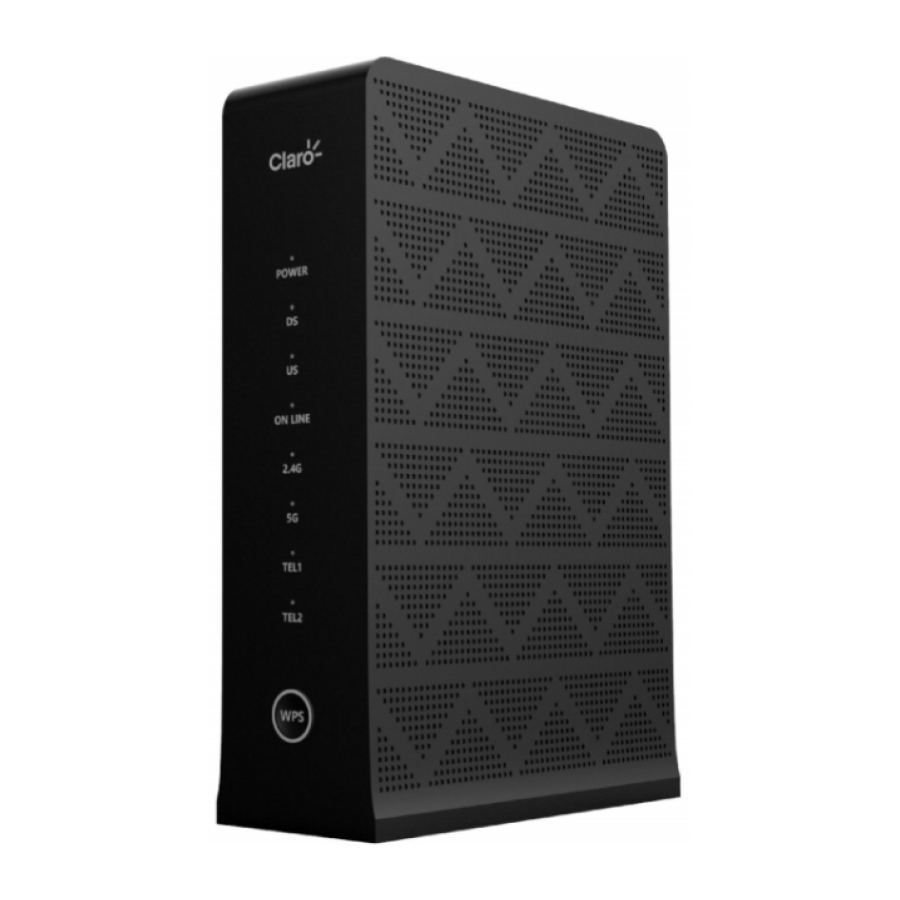
Page 11: Appearance
2. Appearance The OG3000's front panel provides status LED Itemss to indicate correct operation and status. Items Description POWER Power status Items Indicates the status of data reception Indicates the data transmission status Shows the status of the network connection. When the cable of network is not Molex ONLINE connectors or the signal light goes out. - Page 12 Power connectors connection. CABLE IN RF connection interface cable. ETHERNET RJ-45 network cable (10/100 / 1000BaseT integrated) Connection interface. RJ11 Telephone line connection interface Reset the device. Press for more than 5 seconds and the OG3000 will reset to factory RESET settings.
-
Page 13: Installation
Install the device in a central location in your home or office to ensure maximum wireless coverage. 1. Choose a suitable and safe location to install OG3000. 2. Connect one end of the cable to the corresponding cable connector on the back of the OG3000, and... -
Page 14: Network Status
4. Wait for OG3000 to connect normally. This process can take 3 to 5 minutes. When all the Itemss on the front panel of the OG3000 (POWER, DS, US, 2.4G, 5G, ONLINE, TEL1, TEL2) are on. The device is online. -
Page 15: Configuration Introduction
4. Configuration Introduction 4.1 Start Session The user can click on the icon in the upper right corner of the WEB GUI. On the login page that appears, use the username: admin, password: admin to enter the configuration interface. -
Page 17: Quick Setup
4.2 Quick Setup This page allows you to configure 2.4G and 5G SSID names and passwords. It is not necessary to select an encryption method and channel parameters. Items Description Wireless name. SSID You can set 1-32 ASCII strings as the EMTA wireless name. You can also configure the wireless function Enable or Disable via the change button on the right side of the SSID field on the page. -
Page 18: Device Mode Setup
4.3 Device Mode Setup Items Description The operating mode of the system. Default router mode 。 Router Mode: EMTA accesses the Internet through a cable modem. In this mode, Device Mode EMTA has NAT, firewall and other network services. Bridge Mode - All network interfaces in EMTA are linked together. There are no network services like NAT or firewall. -
Page 19: Wan Settings
Once this address is changed, the DHCP address pool will automatically update. Subnet Mask LAN subnet mask, the default is 255.255.255.0 4.4.2 WAN Settings This page allows you to configure the EMTA LAN settings as detailed below. Items Description There are two types of WAN port connection modes, DHCP and Static. WAN Connection Type When the WAN port mode is a static IP address, you must configure the IP... -
Page 20: Dhcp Settings
4.4.3 DHCP Settings This page allows you to configure eMTA LAN DHCP configuration, the configuration is described below. Items Description DHCP function switch. Status You can enable or disable the DHCP function here. The default is to enable it. Start address of the DHCP address group. Start Address Here you can configure the starting address of the LAN DHCP address group. -
Page 21: Dhcpv6 Settings
LAN address. When disabled, the EMTA CPE obtains the DNS address from the EMTA WAN DNS address. 4.4.4 DHCPv6 Settings This page is used to configure the DHCPv6 LAN port address set. Items Description Status Enables or disables the DHCPv6 function of the LAN port. Start Address Start address of the DHCPv6 LAN address group. -
Page 22: Dhcp Clients
4.4.6 DHCP Clients This page will display the following information for all hosts connected to the device through DHCP. -
Page 23: Wireless Settings
Items Description Host Computer name. IP Address IP address assigned to the computer by the DHCP server on the device. MAC Address Address MAC of the computer. Expiration Lease time of the IP address assigned by the DHCP server to the host. 4.5 Wireless Settings 4.5.1 Basic Settings This page can configure the basic parameters of 2.4G and 5G. - Page 24 Items Description Global wireless switch. Enable: enables the wireless access point; Status Disable: Turn off the wireless access point (this will prevent you from connecting to the Internet wirelessly). 802.11bgn mode settings. which generally does not need to be changed. Mode 2.4G: The default value is 802.11 b / g / n.
-
Page 25: Hotspot Settings
4.5.2 Hotspot Settings Items Description Wireless SSID index, 2.4G and 5G, each supports 4 SSID, users can choose SSID Index each SSID for configuration. SSID The name of the SSID. Select the SSID encryption method Five types are currently supported: Authentication Type Open (None);... -
Page 26: Mac Filter Settings
Set the filtering mode to the white list. In this case, only the devices in the list can connect to the wireless access point. 4.5.4 Wireless Stations This page shows all the wireless devices connected to the OG3000. Contains the MAC address and IP address of the wireless device. -
Page 27: Wps Settings
4.5.5 WPS Settings You can enable or disable WPS on the page. Its function is the same as the effect of the WPS button on the front panel of the device. It will enable or disable the 2.4G and 5.8G WPS function at the same time. 4.6 Firewall Settings 4.6.1 Basic Settings You can disable or enable the firewall on this page. -
Page 28: Ip Filter Settings
4.6.2 IP Filter Settings This function is used to filter specified IP data packets. All IPs added to the table will be filtered and will not be forwarded. -
Page 29: Port Filter Settings
4.6.3 Port Filter Settings This function will prohibit the passing of data for the specified protocol in the specified port range. -
Page 31: Url Filter Settings
4.6.4 URL Filter Settings This function is used to filter the Internet behavior of the device and disable or allow access to the specified URL. When Disable is selected for Mode, the function is disabled When Blacklist is selected for Mode, access to URLs added to the list is blocked. ... -
Page 32: Mac Filter Settings
4.6.5 MAC Filter Settings The MAC filter function is to allow or block access to external networks based on the MAC address. Any MAC address added to the table will not be able to access the Internet. -
Page 33: Port Forward Settings
4.6.6 Port Forward Settings Items Description IP address IP of the host to be forwarded. Protocol The protocol that must be sent. TCP, UDP, ALL (TCP and UDP). Internal port Internal port number to be forwarded. External Port External port number used for forwarding. -
Page 34: Port Trigger Settings
4.6.7 Port trigger Settings This feature means that the data flow comes from the host and port (activation port) of the internal network, automatically opens the designated port (open port) of the gateway WAN interface and forwards the data flow pointing to the open port of the WAN port for This host on the internal network. - Page 35 Click the added button, a dialog box will appear, you can set the rules. Items Description MAC address MAC address of the Internet device. Date You can check the day or several days of the week. Period Time period setting, precision is 1 minute. Type There are two types of parental controls: Allow and Prohibit.
-
Page 36: Mac Passthrough
4.6.9 MAC Passthrough This feature allows the CPE connected to the device to penetrate the NAT of the device and obtain the IP directly from the front-end DHCP server. Just fill in the MAC address of the CPE in the table below. The number of CPEs supported by the device is 32. -
Page 37: Dmz
4.6.10 DMZ The DMZ (demilitarized zone) can expose hosts under the LAN port of the device to the external network. The external network only needs to access the IP of the WAN port to access the hosts under the LAN port. Users can remotely access hosts under the LAN port. -
Page 38: Dos Protection
4.6.11 DoS Protection On this page, you can configure options to prevent Dos attacks, which can prevent various Dos attacks from the network. Before enabling DoS Protection, make sure the firewall is turned on. If you need to enable the feature, you can check all types of attacks, click the Save button, and then click the Save &... -
Page 39: Upnp Settings
4.6.12 UPnP Settings Universal Plug and Play ( UPnP ) is a common point-to-point network architecture for PCs and smart devices (or instruments), especially in homes. UPnP is based on Internet standards and technologies (such as TCP / IP, HTTP, and XML) that allow such devices to automatically connect and work with each other, making networks, especially home networks, possible for more people. -
Page 40: Advanced Settings
4.6.13 Advanced settings This page contains some advanced settings for the firewall. Items Description PPTP Enable or disable the PPTP protocol of the device. L2TP Enable or disable the device's L2TP protocol. IPSEC Enable or disable the IPSEC protocol of the device. Wan Blocking Enable or disable ping on the WAN port. -
Page 41: System Management
4.7 System Management 4.7.1 TR069 Settings This page can be used to configure related TR069 management parameters. Items Description Status Enable or disable the function or n TR069 of the device. ACS URL ACS server URL. Port ACS server port. ACS User Name Username for the device to connect to the ACS server through TR069. -
Page 42: System Routes
4.7.2 System Routes This page , you can view system routing table. Items Description Destination address, used to identify the destination address or destination Network Address network of the IP packet. A subnet mask allows you to identify which part of an IP address is reserved Subnet Mask for the network, and which part is available for host use. - Page 43 Items Description Destination address, used to identify the destination address or destination Network Address network of the IP packet. A subnet mask allows you to identify which part of an IP address is reserved Subnet Mask for the network, and which part is available for host use. Next hop IP address, indicating the next router that the IP packet passes Gateway through.
-
Page 44: Time Management
4.7.4 Time Management On this page, you can configure the system time to local time, or configure the NTP server to synchronize the system time. Items Description Current Time Show current system time. NTP Status Enable or disable NTP. NTP Server 1 IP address of the first NTP server. -
Page 45: User Management
4.7.5 User Management The system supports three accounts, administration account, user account and operator account. After logging in with the administrator account, the user names and passwords of all three accounts can be changed. 4.7.6 Settings Management This page can export the current operating parameters of the device to a local file or import a new configuration file. -
Page 46: Factory Restore
4.7.7 Factory Restore On this page, you can restore device settings to factory settings, and you can resolve exceptions caused by configuration errors. -
Page 47: Device Reboot
4.7.8 Device Reboot The device can be restarted on this page. 4.8 DICSIS Management 4.8.1 DOCSIS Status This page can view the operating information of the cable modem. Done "indicates success. If it shows" In Progress "for a long time, it means it fails. -
Page 48: Signal Information
Items Description Initialize Hardware Initialize the system hardware. Acquire Downstream Channel The CM locks and synchronizes the downstream channel. The CM locks the upstream channel and gets its parameter Acquire Upstream Parameters information. Ranging Automatic range and transimit level adjustment. The CM requests the IP address and other network Obtain IP Address parameters through DHCP. - Page 49 Downstream Channels Items Description Frequency Frequency of this channel in MHz. Modulation Downlink channel modulation method.Supports 256QAM and 64QAM. Channel ID of the downstream channel. Power RF input sensitivity level in dBmV. Signal noise rate. Unerroreds Number of correct packets. Correcteds Number of fixable packets.
-
Page 50: Interface Information
Channel RF output level in dBmV. Power Symbol rate in Ksym/s. Symbol Rate ID of the upstream channel. 4.8.3 Interface Information This page can view the CM's IP address, MAC address, configuration file, and other information. Items Description Serial number CM serial number. -
Page 51: Frequencies Cache
4.8.4 Frequencies Cache On this page, you can view the downlink frequency of the CM cache, as well as add and remove frequencies. For the added frequency, the CM will scan the frequency first when connected next time. -
Page 52: Docsis Log
4.8.5 DOCSIS Log This page records the logs generated when the device is online and used. Items Description Time System time when registration occurred. The priority of the records. Notice: NoticeTip Info Priority Error: Error message Critical: Important Information Count The number of times this record appears. -
Page 53: Provisioning File
4.8.6 Provisioning File This page can view the data information of the configuration file obtained by the CM. You can also download the configuration file to your local computer by clicking the "Download Flat File" button below. -
Page 54: Version Information
4.8.7 Version Information This page can view basic EMTA information, including information on software and hardware versions, etc. Items Description Manufacturer Device manufacturer. Model Product model. Compatible Standard s Standards supported by the device. Booter Version Booter version. Hardware Version Hardware version. -
Page 55: Mta Management
4.9 MTA Management 4.9.1 MTA Ststus This page shows the MTA provisioning status, which can help you locate the MTA offline. Items Description Obtain IP Address IP address obtained by MTA. Secure communication MTA secure communication status. Download Provisioning File Name of the configuration file obtained by the MTA. -
Page 56: Interface Information
4.9.2 Interface Information This page can view MTA IP information and telephone line status. Items Description MTA MAC Address MTA MAC address. MTA IP Address IP address obtained by MAT from the DHCP server. Interface Status Registration status of the telephone line. Hook Status Telephone status. -
Page 57: Status Of The Leds
5. Status of the LEDs The LED Items on the front panel is the most direct way for operation and maintenance engineers to locate the problem. The following table defines the status of each Items: On = LED on, Off = LED off, Flashing = LED flashing, X = Not applicable. POWER ONLINE 2.4G... -
Page 58: Troubleshooting
6. Troubleshooting If there is a problem with the device, the following methods do not solve the problem, you can try to solve it by restoring the factory. If that doesn't work, please contact our engineers to solve it. Note: Press the RESET button on the rear panel for more than 5 seconds, or operate on the page according to section 4.7.7. - Page 59 2. Contact your ISP and verify if the assigned phone number is correct. 3. If it still can't be solved, try to replace the device. 4. If it still can't be solved, please contact our engineers to locate the problem.
Need help?
Do you have a question about the OG3000 and is the answer not in the manual?
Questions and answers