Table of Contents
Advertisement
Quick Links
General Information
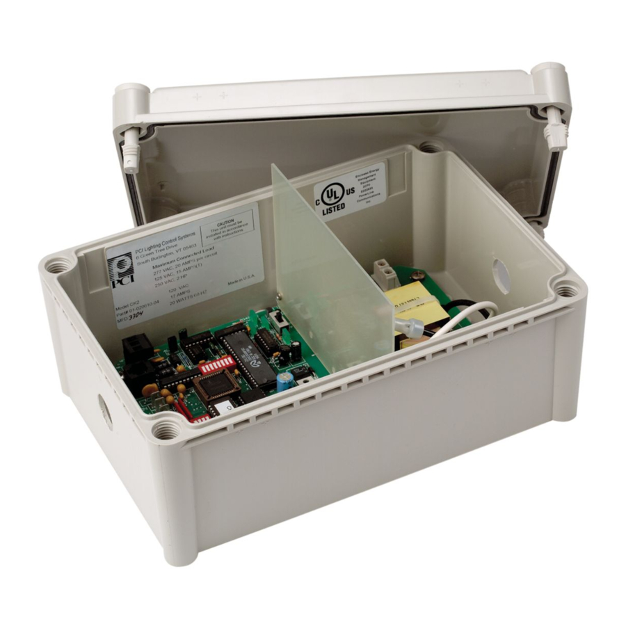
The ControlKeeper-2
is shipped in one package and is
®
configured with a 120V transformer or a 277V transformer.
The two relays are mounted in the high voltage compart-
ment. The logic board and inputs are located in the low volt-
age compartment. The following information describes the
ControlKeeper-2
installation. For programming information,
®
refer to the Keeper Enterprise Software Manual.
Getting Started
1. Do not discard these installation instructions. Please keep
for future reference and operation information.
2. Always disconnect all power before wiring.
3. Use only as intended and at the listed voltage.
4. All installation service must be performed by qualified
personnel or service technicians.
5. Install in accordance with National Electrical Code and
any other codes that may apply.
6. High Voltage is present inside the lighting enclosure. Use
extreme caution when performing maintenance on this
equipment. Failure to follow this warning and proper safety
procedures could result in severe injury or death and/or damage
to the equipment.
7. Document all wiring that is terminated to the relays so that
the lighting control equipment can be properly configured
and programmed for operation.
8. It is recommended that all low voltage wiring be done with
power removed to the logic board to protect components
from potential shorts during the wiring process.
Mounting the Enclosure
1. Choose a dry location convenient to the circuits being
controlled.
2. Mount the panel on a firm surface using predrilled holes.
3. Connect the enclosure to the circuit breaker panel using
conduit into the punch holes provided.
4. Remove all cuttings and dirt.
Note: Make certain that high voltage and low voltage
wiring enters the enclosure separately. High Voltage wir-
ing should be brought into the right section of the enclo-
sure. Low Voltage wire should enter in the low voltage
wiring compartment on the left side of the enclosure.
Failure to separate high voltage from low voltage wiring may
cause interference with logic board function.
Wiring the Transformer
The ControlKeeper-2
is factory configured with a 120V tran-
®
former or a 277V transformer. The transformer voltages are
color-coded. The 120V transformer has the power wired to
the black wire and the 277V transformer has the power wired
to the orange wire. The neutral is the white wire.
Cooper Controls
203 Cooper Circle, Peachtree, Ga 30269
800-553-3879
www.coopercontrol.com
ControlKeeper
2
®
Connect wires to the transformer. You must provide a dedi-
cated circuit with circuit protection for the transformer.
Low Voltage Compartment
Neutral = White
Connecting Relay Loads
Relay Notes:
1. The standard relay is rated for single-pole load use only.
Connection of 2 pole circuits/loads to the relay will void the
equipment warranty and may result in severe injury or death,
and/or damage to the equipment.
2. Relay ratings are 120 or 277 volt, 20 amp maximum.
3. Relay terminal blocks have a maximum limit of 10AWG
wire.
High Voltage Compartment
NETWORK
C19
R49
R8
RP2
Q2
+
F1
J51
S4
-
F2
L1
L3
R57
S
MOV8
C50
L34
Q3
U47
MOV7
C39
C62
R56
C55
S1
C37
F3
L4
C59
R13
C71
C36
ON
U8
CH1
C38
I1
1
BR1
+24
C2
OFF
C1
ON
D99
CH2
+24
SD1
SR1
OFF
C99
GND
C80
+
U3
U4
C53
C52
C81
R7
CX2
U30
R7A
L5
R7B
Q1
Q4
CX1
C100
U32
C83
C58
C82
U7
X1
S5
J2
R112
C31
C21
RESET
R111
S3
High voltage and low voltage
wiring entering the enclosure
Line = 120V (Black),
277V (Orange)
Transformer Wiring Information
InstallatIon sheet
Model # CK2-120-nC
Model # CK2-120-no
Model # CK2-277-nC
Model # CK2-277-no
RELAY 1
SN2
MOV2
TF1
SN1
RELAY 2
MOV1
120V Transformer
Line = Black
Neutral = White
277V Transformer
Line = Orange
Neutral = White
Advertisement
Table of Contents

Related Manuals for Greengate ControlKeeper 2 CK2-120-NC

Summary of Contents for Greengate ControlKeeper 2 CK2-120-NC
- Page 1 InstallatIon sheet Model # CK2-120-nC ControlKeeper ® Model # CK2-120-no Model # CK2-277-nC Model # CK2-277-no General Information The ControlKeeper-2 is shipped in one package and is Connect wires to the transformer. You must provide a dedi- ® configured with a 120V transformer or a 277V transformer. cated circuit with circuit protection for the transformer.
- Page 2 ® closure and Digita Switch inputs. If a combination of contact ® It is possible to use a contact input photosensor and Greengate input switches and Digita Switches are being used, the com- ® Motion Sensors in conjunction with the lighting control system.
- Page 3 Please contact technical support if it is necessary to power 2. Run a length of the Digita Switch LC or Belden cabling ® additional sensors beyond the numbers listed above. These from the Digita Switch Gateway location to the low voltage ®...
- Page 4 Continue this process through the network making certain Acceptable Suggested Cable to observe polarity. When finished, the two end panels will Lighting Network Wiring have a single pair of wires coming into the network terminal Belden 7854A Standard CAT 5 block while all middle panels in the network will have two Standard CAT5e Belden 1583A...
- Page 5 In addition, other periph- be energized. In the ALL OFF position, the relay coils will be eral devices provided by Greengate may plug into this port for de-energized. The middle, AUTO, position allows the relays communication purposes.
- Page 6 Item Reference Drawings 1. DC Ground 11. High/Low Voltage Barrier (Do not connect to Earth or Conduit Ground) 12. Relay Output 1 2. Option Select Switch 13. 120V (Black) or 277V (Orange) 3. Switch Input Channels 14. Neutral (White) 4. RS232 – RJ12 Connector 15.
- Page 7 Cooper Controls and identified with the Greengate brand are warranted to be free from defects in material and workmanship and shall conform to and perform in accordance with seller’s written specifications for a period of : •...
Need help?
Do you have a question about the ControlKeeper 2 CK2-120-NC and is the answer not in the manual?
Questions and answers