
Related Manuals for Muck-Truck Muck-Truck Mk IV Dumper


Summary of Contents for Muck-Truck Muck-Truck Mk IV Dumper
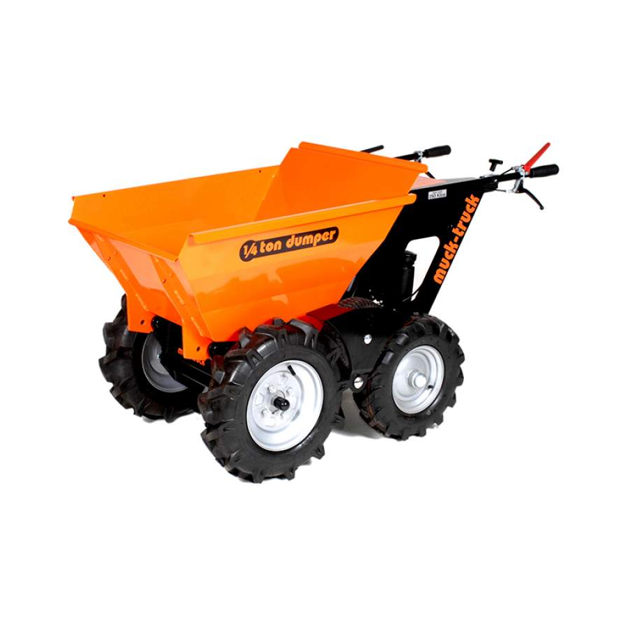
- Page 1 Muck-Truck Mk IV Dumper MAX Mk II Dumper Owner, Operation, Accessories & Parts Manual Models Muck-Truck Mk IV Dumper MAX Mk II Dumper Starting with Serial Number 101 03737210 12/08 ENGLISH Printed in USA...
-
Page 2: Table Of Contents
The undersigned of Niche Product Sales LLC declare that the Pedestrian Dumper Trucks: Category: Gasoline 4-Stroke Pedestrian Dumper Model: Muck-Truck Mk IV Dumper / MAX Mk II Dumper Conform with the essential Health and Safety requirements of the EEC Directive. 98/37/EC (Edition L 207) Previously 89/392/EEC – 93/94/EEC Amendment Basic Noise Emission Standard –... -
Page 3: Assembly
Ensure that both sides are mounted at the same length. Figure 2 Muck-Truck Mk IV handles have one mounting location. 5. Insert 5/16 x 2" hex bolt from Manual Package into remaining hole and secure with washers and nut Cowling removed from shipping bolt. -
Page 4: Safety
SAFETY SAFETY ALERT SYMBOL Read the entire Owner/Operator manual. If the operator or the mechanic cannot read the manual, it is the owner’s These are safety alert symbols. They responsibility to explain it to them. Only the user can mean: prevent and is responsible for accidents or injuries •ATTENTION! occurring to themselves, other people or property. -
Page 5: Controls And Features
Do not use a pressure washer directly on engine Keep fuel nozzle in contact with the rim of the fuel tank or electronics. container opening at all times until fueling is complete. Do not use a nozzle lock-open device. Fuel is highly flammable and its vapors are explosive. Handle with care. -
Page 6: Operation
OPERATION CONTROLS AND FEATURES Clutch Lever (Figure 6) See CONTROLS AND FEATURES on page 5. With a forward or reverse gear selected, gently engage Throttle Lever (squeeze) the clutch lever to move the unit forward or (Figure 4) backward. Release the clutch lever to stop motion. The throttle lever controls the choke position and the engine speed. - Page 7 Skip Release Lever 3. Remove accessory or tilt forward to gain access to fuel tank. (Figure 8) 4. Clean fuel cap and surrounding area to prevent dirt Squeeze the skip release lever to release the skip lock. from entering fuel tank. Release the skip release lever to engage the skip lock.
-
Page 8: Maintenance
To Empty Skip To Reset Skip 1. Stop unit and release parking brake lever. 1. Pull back on the skip. 2. Release the skip lock by squeezing the skip release 2. Engage the skip lock by releasing the skip lock lever. -
Page 9: Service And Adjustments
SERVICE AND ADJUSTMENTS LEVER ADJUSTMENTS (Figure 10) Primary clutch and skip release cable adjustments are made at the levers. To adjust: 1. Loosen lock nut (item 1). 2. Adjust cable by rotating adjustment nut (item 2). Moving adjustment nut away from the lever will result in earlier engagement. - Page 10 DRIVE BELT REPLACEMENT (Figure 14) Removal 1. Remove two 5/16" hex bolts retaining bottom panel at front of unit. 2. Place unit in service position (see SERVICE POSITION above). 3. Remove remaining four 5/16" hex bolts retaining the bottom panel and remove the panel. 4.
- Page 11 NOTES GB – 11...
-
Page 12: Parts List
PARTS LIST COWLING, CONTROLS & SKIP GB – 12... - Page 13 Washer, Flat M8 Reg. 00967115 Locknut, 5/16-18 Nyloc 00111910 Cable Tie .15 x 8.50 03737151 Weldment, Cowling Side Left Hand (Muck-Truck Mk IV) 03795151 Weldment, Cowling Side Left Hand (MAX Mk II) 03737351 Tube, Handle – Left Hand 03737227 Cable, Clutch Control...
- Page 14 MAIN FRAME & DRIVETRAIN Mk II Muck-Truck Mk IV GB – 14...
- Page 15 Locknut 1/2-13 Nyloc 03737105 Wheel Assembly, Power Drive 00961704 Washer, Flat M12 Reg. 03737226 Cap, Vinyl 2.25 x 1.00 (Muck-Truck Mk IV) DP32 Nut, Push Rear Wheel (Muck-Truck Mk IV) 03737104 Wheel Assembly, Left Hand Rear (Muck-Truck Mk IV) 00967070 Bolt, Hex 5/16-18 x 1.00 Gr.
- Page 16 TRANSMISSION AND BELT DRIVE Muck-Truck Mk IV: 12.497" (31.74 cm) MAX: 12.425" GB – 16...
- Page 17 TRANSMISSION AND BELT DRIVE (CONT’D) Item Part No. Qty. Description 05901336 Bolt, Hex 1/2-13 x 3.5 5 FLTD 00967070 Bolt, Hex 5/16-18 x 1.00 Gr. 5 00967115 Locknut, 5/16-18 Nyloc 00961702 Washer, Flat M8 Reg. 05952600 Bolt, Hex 5/16-18 x 2.50 Gr. 5 03737124 Shift Rod Assembly (Includes items 37, 38 and 39) 00960050...
-
Page 18: Accessories
ACCESSORIES TOW HITCH KIT – 795710 Ball & Assembly and Installation Hardware (Not WARNING: AVOID INJURY. Read and Included) understand the entire Safety section before Receiver installing and using accessories. Weldment Figure 15 SAFETY RULES • Always wear gloves when handling accessories. •... - Page 19 • Always wear gloves when handling accessories. • Skip extensions do not increase weight capacity of unit, only volume capacity. DO NOT exceed maximum weight capacity. • Extension kit is designed to fit Muck-Truck Mk IV and MAX Mk II skips. Installation (Figure 17) 1.
- Page 20 WHEEL EXTENSION KIT – 795713 Assembly and Installation WARNING: AVOID INJURY. Read and understand the entire Safety section before installing and using accessories. SAFETY RULES • Always wear gloves when handling accessories. Figure 18 • Remove load from unit before installing wheel extension kit.
- Page 21 NOTES GB – 21...
- Page 22 SNOW PLOW KIT – 795714 Assembly and Installation WARNING: AVOID INJURY. Read and understand the entire Safety section before installing and using accessories. SAFETY RULES • Always wear gloves when handling accessories. • The weight of the snow plow can cause the skip to drop slightly against the lock plate if the Figure 21 skip-release lever is squeezed.
- Page 23 SNOW PLOW KIT – 795714 (CONT’D) Parts List Item Part No. Qty. Description 03737116 Grip, Handle 22 mm x 135 mm 03772165 Weldment, Snow Plow Pivot 03772265 Weldment, Moldboard 03772465 Weldment, Skid 03772565 Plate, Scraper Clamp 03772402 Scraper, 48" Poly 03772403 Pin, Angle 03772665...
- Page 24 RAMP KIT – 795715 Debris Secure both container Assembly and Installation sides with lynch pins. WARNING: Ramp has a maximum capacity of 992 lb. (450 kg) DO NOT overload. SAFETY RULES • Always wear gloves when handling ramp components. • Approximate ramp weights are 77 lb. (35 kg) for the upper section and 44 lb.
- Page 25 RAMP KIT – 795715 (CONT’D) Parts List Item Part No. Qty. Description 03774351 Weldment, Ramp Platform 03774451 Weldment, Ramp Lower 03774551 Weldment, Ramp Leg 03774651 Weldment, Ramp Pin 03774751 Strap, Ramp Support 03774951 Plate, Ramp Hook – US 00960114 Bolt, Hex 1/2-13 x 1.50" 00960704 Washer, Regular Flat .50"...
- Page 26 FLAT BED KIT – 795718 Handle Assembly Assembly and Installation 3/8" Lock WARNING: AVOID INJURY. Read and Nuts understand the entire Safety section before Flat Bed installing and using accessories. Assembly SAFETY RULES • Always wear gloves when handling accessories. 3/8 x 1"...
- Page 27 BULK SKIP KIT – 795719 2. Attach handle assembly to the skip assembly using four 3/8 x 1" carriage bolts, four M8 washers and Assembly and Installation four 3/8" lock nuts. Do not fully tighten. See Figure 28. 3. Attach handle assembly to skip frame with four 3/8 WARNING: AVOID INJURY.
-
Page 28: Warranty
WARRANTY Serial Number: Warranty is 12 calendar months from date of sale for Consumers and 90 days for units used in the Commercial Sector. Under the following conditions: • Routine maintenance completed in accordance with Owners Manual. • Returned defective parts are approved by Niche Product Sales LLC. •... - Page 30 Niche Product Sales LLC 586 Mercantile Place Port Saint Lucie, FL 34986 www.mucktruck.com...
Need help?
Do you have a question about the Muck-Truck Mk IV Dumper and is the answer not in the manual?
Questions and answers