Advertisement
Quick Links
Advertisement

Summary of Contents for ESPER POWERBOX
- Page 1 U s e r ' s M a n u a l...
-
Page 2: Table Of Contents
Table of Contents Overview 2 Accessories 4 Safety Warning 4 Connecting the PowerBox to Cameras 5 Powering the TriggerBox 7 Troubleshooting 10 Technical Specifications 11 Two-Year Warranty 12 1 ... -
Page 3: Overview
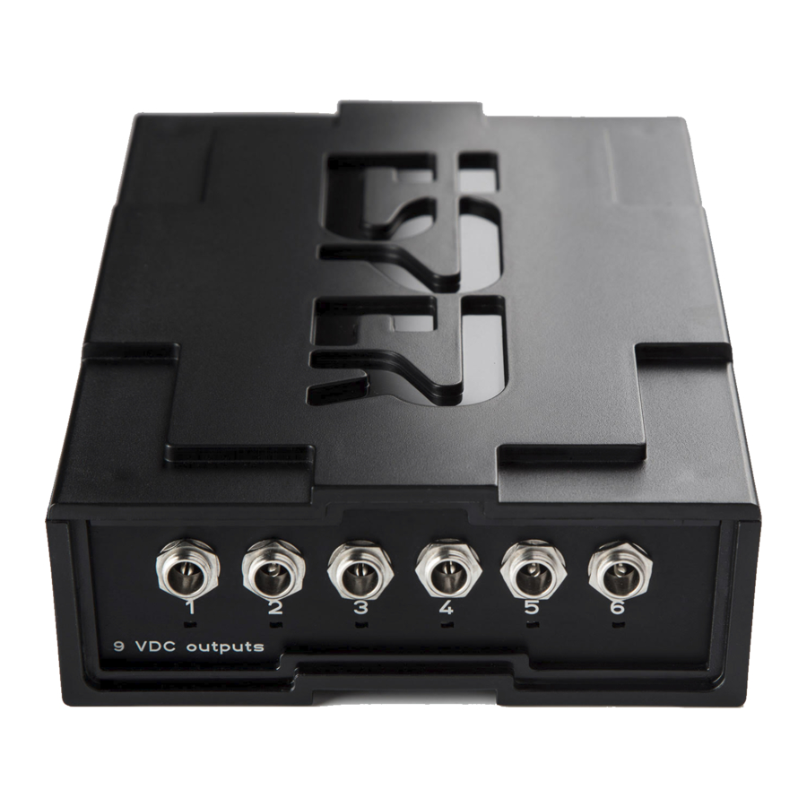
Overview Thank you for buying an ESPER PowerBox. The PowerBox allows you to connect up to 6 cameras and provide safe and reliable power to all cameras from a single wall outlet. Please refer to the instructions below to properly understand the functionality of hardware in your multi-camera setup. ... - Page 4 Multi-region universal power supply ● If you purchased the ESPER PowerBox as a bundle it may include additional cabling. Note: P lease check all the contents of your order upon receipt of goods. If you receive a delivery ...
-
Page 5: Accessories
Accessories ESPER PowerBox is designed to stack neatly together with the TriggerBox units. Multi-camera trigger solution can be purchased at h ttps://www.esperhq.com/product/multiple-camera-trigger-triggerbox/ . Camera power cables and DC-couplers are available for many different cameras makes and models. ... -
Page 6: Connecting The Powerbox To Cameras
Step 1. Powering up the PowerBox Connect the 48V PSU 4 pin connector to the PowerBox connection on the front panel ( fig.1 a) . Figure 1. ... - Page 7 Step 3. Connecting your cameras to the DC Couplers Once you've connected the coupler to the PowerBox, take the battery end of the coupler and place it inside your cameras battery compartment. Make sure the lid for the battery slot is closed otherwise ...
-
Page 8: Powering The Triggerbox
Step 1. Connecting the USB cable to the PowerBox Connect one end of the USB-C cable into the USB-C port on the front of the PowerBox. Ensure the cable is completely plugged in ( f ig.4 a ) . ... - Page 9 Step 3. Power up the PowerBox Power up the PowerBox using the provided power supply. The reset button will have a green light lit if it is receiving power. After a few seconds, the TriggerBoxes mode button should start flashing and ...
- Page 10 Figure 7. E SPER PowerBox powering the TriggerBox in 'Smart Trigger (Blue Mode)' Note: U sing short USB-C cables are ideal as this keeps your setup looking tidy and professional. We can supply USB-C to USB-C cables in short lengths. Visit ...
-
Page 11: Troubleshooting
Fix: All cables supplied by Esper have been fully tested and provide a solid connection as these cables have a screw-on connector meaning there is no risk of the cable coming loose when connecting up your ... -
Page 12: Technical Specifications
Technical Specifications Dimensions 113mm W x 40mm H x 175mm D Weight 685g Enclosure High Impact Lexan Polycarbonate with 5251 Aluminium Face Plates Enclosure Finish Matt Black Textured Face Plate Finish Matt Black Anodised Power Input 48VDC lockable 4 Pin DIN Connection ... -
Page 13: Two-Year Warranty
ESPER, shall have no responsibility. The warranty covers all defects encountered in normal use of the ESPER PowerBox, and does not apply in any of the following cases: 1. Loss of or damage to the ESPER PowerBox due to abuse, mishandling, improper packaging by ...
Need help?
Do you have a question about the POWERBOX and is the answer not in the manual?
Questions and answers