Table of Contents
Advertisement
Quick Links
DKM-0224 User Manual
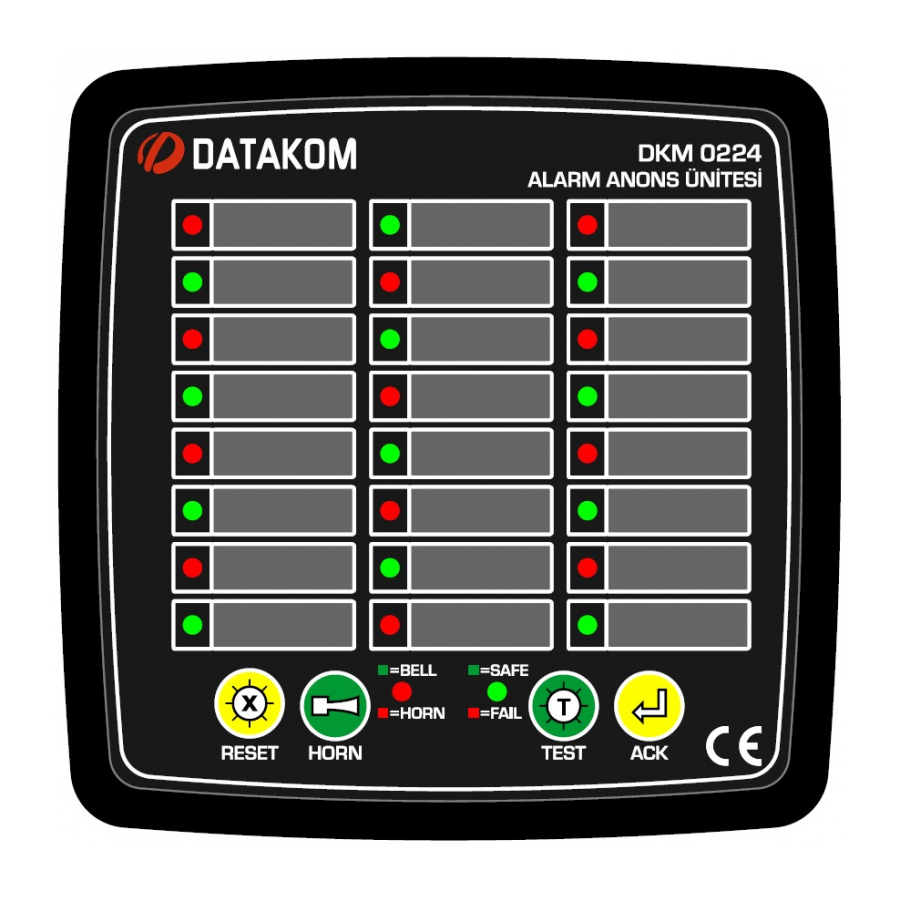
DKM-0224
ALARM ANNUNCIATOR
DESCRIPTION
The DKM-0224 is an 24 channel, 144x144mm
alarm annunciator designed to be used in energy
and automation systems.
Optically isolated digital inputs are equipped with
noise cancelling filters and are capable of
operating smoothly in high electrical noise
environments. The detection delay of inputs are
adjustable between 2 and 500ms.
The module features 3 relay outputs rated at
5Amp. Relays provide Horn, Bell and Internal
Failure functions. An additional buzzer is provided
inside the unit for audible alarms.
The unit features ultra-bright, bicolor (red-green)
led indicators. Alarms may be assigned to
different priority levels in order to reduce
confusion.
Using front panel pushbuttons, alarms may be
acknowledged and reset, the unit tested.
The configuration of the module is performed with
jumpers placed on the back panel. Additional
programming may be performed from the front
panel or through programming software.
The isolated RS-485 MODBUS RTU
communication port is free from ground potential
differences and allows safe transfer of measured
parameters to automation and monitoring
systems.
It is possible to monitor the module and keep
records with Datakom Rainbow+ software.
The supply input is isolated from other terminals.
The module has two supply versions being 19-
150V-DC or 85-305V-AC (88-400V-DC).
When the unit detects a fault signal from an input,
the related alarm led becomes active.
FAST FLASH: At the first detection of the fault.
SLOW FLASH: Activated when the ACK(alarm
acknowledge) pushbutton is pressed and if the
fault is still active.
STEADY ON: Activated if the fault signal
disappears at SLOW FLASH condition.
LED OFF: The alarm led turns off when RESET
pushbutton is pressed and fault signal is not
present.
When a fault signal is detected, the internal
buzzer turns on with a period of 1 second. If ACK
pushbutton is pressed, the buzzer turns off. If
ACK is not pressed within 1 minute, then it
switches to slow sound mode (beeps once every
10 seconds.)
HORN RELAY: If any "red" alarm led turns on,
then the horn relay will also turn on. The relay
turns off when ACK pushbutton is pressed.
BELL RELAY: If any "green" alarm led turns on,
then the bell relay will turn on. The relay turns off
when ACK pushbutton is pressed.
WATCHDOG RELAY: At startup the relay turns
on. If the board fails, then it turns off.
HORN/BELL LED: If the HORN relay turns on,
the "red" led turns on. If the HORN relay is not on
and if the BELL relay is on, then the "green" led
turns on. If both relays are off then the led is off.
SAFE/FAIL LED: If an internal fault condition is
detected at self-test, then this led will turn on
"red", else it turns on "green".
-1-
V-1.0
(11.08.2016)
FEATURES
Advertisement
Table of Contents

Related Manuals for Datakom DKM-0224

Summary of Contents for Datakom DKM-0224
- Page 1 ALARM ANNUNCIATOR DESCRIPTION FEATURES When the unit detects a fault signal from an input, The DKM-0224 is an 24 channel, 144x144mm the related alarm led becomes active. alarm annunciator designed to be used in energy and automation systems. FAST FLASH: At the first detection of the fault.
- Page 2 DKM-0224 User Manual V-1.0 (11.08.2016) SAFETY NOTICE CAUTION Failure to follow below instructions will result in death or serious injury Electrical equipment should be installed only by qualified specialist. No responsibility is assured by the manufacturer or any of its subsidiaries for any consequences resulting from the non-compliance to these instructions.
-
Page 3: Table Of Contents
DKM-0224 User Manual V-1.0 (11.08.2016) TABLE OF CONTENTS 1. INSTALLATION INSTRUCTIONS 1.1. FRONT AND BACK PANELS 1.2. MECHANICAL INSTALATION 1.3. ELECTRICAL INSTALLATION 2. PUSHBUTTON FUNCTIONS 3. LED FUNCTIONS 4. SETTINGS 4.1. JUMPER SETTINGS 4.2. SIGNAL LED RED/GREEN SETTINGS 4.3. BUZZER SETTINGS 5. -
Page 4: Installation Instructions
DKM-0224 User Manual V-1.0 (11.08.2016) 1. INSTALLATION INSTRUCTIONS Before Installation: Read the user manual carefully, determine the correct connection diagram. Remove all connectors and mounting brackets from the unit, then pass the unit through the mounting opening. Put mounting brackets and tighten. Do not tighten too much, this can brake the enclosure. - Page 5 DKM-0224 User Manual V-1.0 (11.08.2016)
-
Page 6: Front And Back Panels
DKM-0224 User Manual V-1.0 (11.08.2016) 1.1 FRONT and BACK PANELS 1.2 MECHANICAL INSTALLATION Panel Cutout Required Panel Depth... -
Page 7: Electrical Installation
DKM-0224 User Manual V-1.0 (11.08.2016) 1.3 ELECTRICAL INSTALLATION Do not install the unit close to high electromagnetic noise emitting devices like contactors, high current busbars, switchmode power supplies and the like. Although the unit is protected against electromagnetic disturbance, excessive disturbance can affect the operation and measurement precision ... -
Page 8: Pushbutton Functions
DKM-0224 User Manual V-1.0 (11.08.2016) 2. PUSHBUTTON FUNCTIONS BUTTON FUNCTION If the pushbutton is pressed all fault leds turn off, Horn and Bell relays are released. If the fault signal still persists, the fault alarm re-appears again. This button is also used in settings menu. - Page 9 DKM-0224 User Manual V-1.0 (11.08.2016) 3. DISPLAY AND RELAYS Signal Leds Alarm Labels (1-24) (1-24) Reset Button Ack Button Horn Button Test Button Fail/Safe Led Horn/Bell Led relay is on, then the “green” led turns on. SIGNAL LEDs: There are 24 red/green adjustable signal leds on the panel.
-
Page 10: Settings
DKM-0224 User Manual V-1.0 (11.08.2016) 4. SETTINGS 4.1 DIP-SWITCH SETTINGS The main configuration of the unit is done with DIP switches located on back panel.There are 8 Dip Switch on the unit and the settings are described below. 1-2-3. Switch: 4. -
Page 11: Modbus Communication
DKM-0224 User Manual V-1.0 (11.08.2016) 5. MODBUS COMMUNICATION 5.1 INTRODUCTION The unit has serial communication port that can be integrated to automation systems. Serial port is a standart RS-485 MODBUS-RTU isolated from supply input and measuring terminals. Therefore, the unit survives under harsh industrial conditions without any damage. -
Page 12: Commands
DKM-0224 User Manual V-1.0 (11.08.2016) There are 3 parameters for this unit. Function 10 (Write multiple registers) is used for changing the parameter value. ADDRESS NAME DESCRIPTION SIZE R/W TYPE Led Color Setting Red: 1, Led 1-8 Settings 16 BIT... -
Page 13: Technical Specifications
Signal Type: RS-485 2006/95/EC (LVD) EN 61010 (safety) Protocol: Modbus RTU 2004/108/EC (EMC) EN 61326 (EMC) Data Rate: 9600-19200baud Isolation: 1000V AC, 1 minute DATAKOM Electronics Ltd. Tel: +90-216-466 84 60 Fax: +90-216-364 65 65 e-mail: datakom@datakom.com.tr http: www.datakom.com.tr -13-...
Need help?
Do you have a question about the DKM-0224 and is the answer not in the manual?
Questions and answers