Table of Contents
Advertisement
Quick Links
Operating Instructions
Southwire
Triggers
™
®
Wireless Safety Switch System
TSS-01
Read and understand all of the instructions and
safety information in this manual before operating
or servicing this tool.
FAILURE TO OBSERVE THESE WARNINGS
CAN RESULT IN SEVERE INJURY OR DEATH.
TESTING EQUIPMENT
4VR8
Advertisement
Table of Contents

Subscribe to Our Youtube Channel
Related Manuals for Southwire Triggers TSS-01

Summary of Contents for Southwire Triggers TSS-01
- Page 1 Operating Instructions Southwire Triggers ™ ® Wireless Safety Switch System TSS-01 Read and understand all of the instructions and safety information in this manual before operating or servicing this tool. FAILURE TO OBSERVE THESE WARNINGS CAN RESULT IN SEVERE INJURY OR DEATH.
-
Page 2: Table Of Contents
Table of Contents Description....................2 Safety....................3-4 Purpose of this Manual.................4 Identification………………………………………………………..5-10 Pairing Instructions…………………………………………………..…11 System Operation................12-14 Battery Charging and System Storage..........14 Parts List.................... 15 Specifications…..................15 Warranty..................16-18... -
Page 3: Description
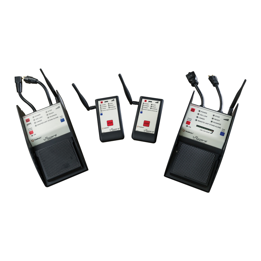
Description The Triggers dual remote foot pedal system is designed for power ® control and safety for all your cable pulling and feeding applications. The person operating the puller and the person feeding the wire both have control over the puller’s motor. The hand held units serve a dual purpose. -
Page 4: Safety
Safety Safety is essential in the use and maintenance of Southwire Tools and Equipment. This instruction manual and any markings on the tool pro- vide information for avoiding hazards and unsafe practices related to the use of this tool. Observe all of the safety information provided. -
Page 5: Purpose Of This Manual
This instruction manual is intended to familiarize personnel with the safe operation for the Southwire Triggers Wireless Safety Switch ™ ® System. Keep this manual available to all personnel. Replacement manuals are available upon request at no charge at www.southwire- tools.com. -
Page 6: Identification
Master Unit Identification 1. Power Switch 2. Stand Alone Switch 3. Stand Alone On Indicator Light 4. Power Indicator Light 5. Vac Low Indicator Light 6. Linked Indicator Light 7. Master Unit Stand Alone Indicator Light 8. Stop Indicator Light 9. - Page 7 Master Unit Identification cont. VISUAL COMMUNICATION • POWER LIGHT (RED): Indicates unit is powered on • VAC LOW (AMBER): Indicates A/C line voltage has dropped below recommended optimal range • LINKED LIGHT (BLUE): Indicates that unit is linked to the system •...
- Page 8 Remote Unit Identification 1. Power Switch 2. Stand Alone Switch 3. Stand Alone On Indicator Light 4. Power Indicator Light 5. Vac Low Indicator Light 6. Linked Indicator Light 7. Master Unit Stand Alone Indicator Light 8. Stop Indicator Light 9.
- Page 9 Remote Unit Identification cont. VISUAL COMMUNICATION • POWER LIGHT (RED): Indicates unit is powered on • VAC LOW (AMBER): Indicates A/C line voltage has dropped below recommended optimal range • LINKED LIGHT (BLUE): Indicates that unit is linked to the system •...
- Page 10 Hand Held Unit Identification 1. Power Switch 2. Power Indicator Light 3. Charge Indicator Light 4. Linked Indicator Light 5. Stand Alone Indicator Light 6. Stop Indicator Light 7. Ready Indicator Light 8. Running Indicator Light 9. Antenna 10. Signal Strength Indicator 11.
- Page 11 Hand Held Unit Identification cont. VISUAL COMMUNICATION • POWER LIGHT (RED): Indicates unit is powered on • CHARGE (AMBER): Indicates unit is charging • LINKED LIGHT (BLUE): Indicates that unit is linked to the system master/remote • STAND ALONE LIGHT (BLUE): Indicates that either master or remote unit is in stand alone mode •...
-
Page 12: Pairing Instructions
Pairing Instructions System comes from the factory with all units Paired. 1. Turn on Master Unit. 2. Turn on all other units to be paired. 3. Hold down “PAIR” button on Master unit until “LINKED” light begins flashing. 4. Hold “PAIR” button on unit to be paired to Master until the “LINKED”... - Page 13 Operation Before using the Triggers system all battery powered units should be ® fully charged 1. Turn on Master Unit by pressing the power button (1). Power light (4) will indicate power to the unit. 2. Turn on the Remote Unit by pressing the Power button (1). Power light will indicate power to the unit.
- Page 14 Operation cont. MASTER UNIT AS STAND ALONE FOOT SWITCH 1. Plug a 20 amp 120 Volt extension cord into the extension cord input (13). If using a 15 amp motor or less you may plug in a 15 amp 120 Volt extension cord using a 20 amp to 15 amp adaptor plug.
-
Page 15: Battery Charging And System Storage
Operation cont. AMPERAGE DRAW INDICATOR AND LOW VAC INDICATOR The amperage Draw Indicator is scaled to read from 0 to 20 Amps. This is not a safety feature and is to be used for reference only. The unit itself does not provide any over amperage protection. -
Page 16: Parts List
TSS-PS 7 PLUG POWER STRIP Specifications • Model# TSS-01 • Width- 21.50” • Stock# 59713201 • Height- 12.54” • Name- Southwire Triggers • Weight- 30 lbs ™ ® Wireless Safety Switch System • Patent Number- U.S. Patent No. • Length- 16.42”... -
Page 17: Warranty
Contractor Equipment electronic components, and Material Boxes. Under this 5-Year Limited Warranty, the following are also ex- cluded and Southwire Company, LLC will have no liability for any of the following: normal wear and tear resulting from product use and damage arising out of misuse, abuse, modification, and improper product maintenance. - Page 18 OTHER WARRANTY, EXPRESSED OR IMPLIED, OTHER THAN THE RELEVANT WARRANTY SPECIFICALLY SET FORTH IN THIS WAR- RANTY SECTION. SOUTHWIRE WILL NOT BE LIABLE FOR ANY IN- CIDENTAL, CONSEQUENTIAL, INDIRECT, SPECIAL, OR PUNITIVE DAMAGES FOR ANY BREACH OF THIS LIMITED LIFETIME WAR- RANTY.
- Page 19 Warranty On Southwire Contractor Equipment cont. 1. All warranty claims must be approved by Southwire’s Tools & Assembled Products Warranty Department prior to return of product. If Southwire determines that a product is defective, Southwire will, at its option, repair or replace defective products or defective product components, free of charge.
- Page 20 1-855-SW-T00LS Toll Free Technical Help Contents Made in USA Product distributed by Southwire Company, LLC One Southwire Drive, Carrollton, GA 30119 ©2016 Southwire Company, LLC. All rights reserved. 3/16 Rev. 0 TSS-01 manual...
Need help?
Do you have a question about the Triggers TSS-01 and is the answer not in the manual?
Questions and answers