
Subscribe to Our Youtube Channel
Summary of Contents for MX MX R10
- Page 1 FRONT LINKAGE MX R10 MX R16 User manual Please read carefully before using MX front linkage UK 361905 AG -0919 Translation of the original manual...
- Page 3 Thanks you for confidence in our product. We are sure it will give you full satisfaction. By taking a few minutes to read this manual, you will be able to obtain the best results from your MX front linkage, extend its lifespan and work in complete safety.
-
Page 5: Table Of Contents
CONTENTS SAFETY REGULATIONS USAGE REGULATION SAFETY STICKERS IDENTIFICATION PLATE DESCRIPTION OPERATING POSITION IMPLEMENT HITCHING IMPLEMENT DISCONNECTING FOLDED ARMS POSITION 10. REAR SUPPORT* 11. PUSH BAR* 12. SHOCK ELIMINATOR* 13. FRONT POWER TAKE OFF (PTO)* 14. ADDITIONAL FRONT HYDRAULIC LINE* 15. 3-WAY SELECTOR* 16. - Page 7 The operator must read this manual before using the product for the first time. Familiarise yourself with: — Safety and operating regulations. — Hitching and unhitching of the implement. — Full use of the controls. Modification reserved 19, rue de Rennes BP 83221 • F - 35690 ACIGNÉ •...
-
Page 8: Safety Regulations
— The tractor/loader/linkage assembly must only be driven by someone who is trained and experienced. — When the tractor is fitted with a front linkage and loader, the user has to unhitch the loader before to using the MX front linkage (please see the loader instruction book for the unhitching proceedure). -
Page 9: Usage Regulation
Caution! Recommendations for fixing the implement, and working on the ground, must be strictly complied with. Any deviation from the requirements described above may cause serious damage, for which MX cannot be held liable. Modification reserved 19, rue de Rennes BP 83221 •... -
Page 10: Safety Stickers
3. SAFETY STICKERS Safety stickers are located on the front linkage. Keep them readable and clean, and change them if damaged. 3T Maxi 4. IDENTIFICATION PLATE The identification plate is located on the right hand side of the headstock. 19, rue de Rennes F - 35690 ACIGNÉ Désignation/ Designation Type / Model / Typ... -
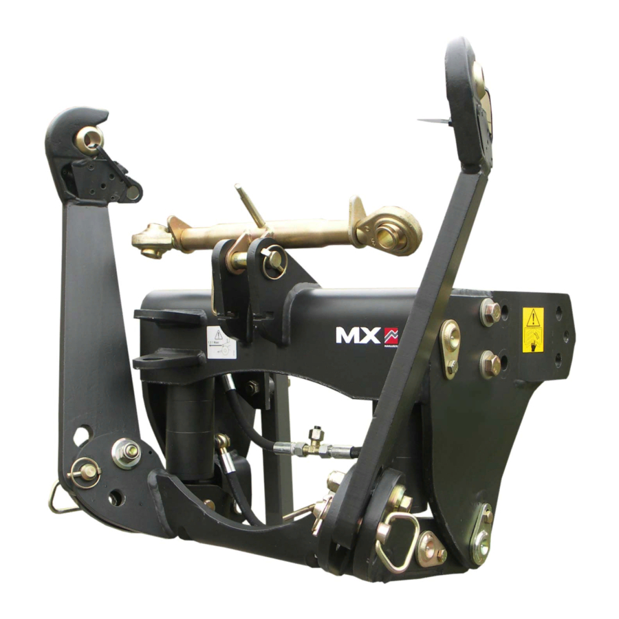
Page 11: Description
5. DESCRIPTION Right arm Left arm Arm pin Linkage frame Top-link yoke Top-link bar Lever locknut Hitch yoke (use a 30 mm diameter pin) 10: Frame 11: Coupler 12: Ball end Modification reserved 19, rue de Rennes BP 83221 • F - 35690 ACIGNÉ •... -
Page 12: Operating Position
6. OPERATING POSITION Caution This operation must be carried out by the driver who must leave the seat and ensure all manoevres are forbidden while he is working on the front linkage. 6.1 Choose a flat and stable area. Pull the parking brake. Turn off the engine. 6.2 Leave the cab and remove the L.H. arm locking pin. 6.3 ... - Page 13 6.4 Swing the arms forwards to the desired position. Position 1: Fixed position. Position 2: Floating position. Arm in floating position. The implement follows the contours of the ground. 6.5 Put the pin back in position, and lock with the locking pin. 6.6 ...
-
Page 14: Implement Hitching
7. IMPLEMENT HITCHING Caution This operation must be carried out by the driver who must leave the seat and ensure all manoevres are forbidden while he is working on the front linkage. The linkage is in working position. 7.1 Open the locking catches on the hitching hooks and hitch up the implement. -
Page 15: Implement Disconnecting
8. IMPLEMENT DISCONNECTING Caution This operation must be carried out by the driver who must leave the seat and ensure all manoevres are forbidden while he is working on the front linkage. 8.1 Lay the implement on some flat stable ground. Operate the tractor’s handbrake. -
Page 16: Folded Arms Position
9. FOLDED ARMS POSITION Caution This operation must be carried out by the driver who must leave the seat and ensure all manoevres are forbidden while he is working on the front linkage. 9.1 Choose a flat and stable area. Raise the front linkage arms. Apply the parking brake and shut off the engine. -
Page 17: Rear Support
9.4 Swivel the arm towards the bac and put the pin and the locking pin back in position. 9.5 Repeat the items 9.3 et 9.4 for the left arm. 10. REAR SUPPORT* This structure is located under the tractor and it reinforces the tractor from the clutch bell housing to the rear trumpet housings. -
Page 18: Shock Eliminator
12. SHOCK ELIMINATOR* The shock absorber function requires that: — The minimum load for Shock Eliminator efficiency corresponds to 20% of the linkage max. capacity. NOTE: The greater the load, the smaller the shock absorber travel must be. — The linkage is never at its maximum height. To attain the shock- absorbed transport position, the linkage must be lowered slightly starting from the upper position. -
Page 19: Additional Front Hydraulic Line
Release the pressure in the hydraulic system to make connecting the hoses easier. 14.2 Control the hydraulic line using the tractor’s control valve or the MX control valve (refer to the "control" section). * According to equipment Modification reserved 19, rue de Rennes BP 83221 •... -
Page 20: Way Selector
There are 3 operating modes: 15.1 "Locking" operation. Usage: this mode is used when the MX front linkage is not being used or for travelling long distances with an implement or a weight (safety in transit). -
Page 21: External Control
A second external control can be fitted on the front linkage to operate another hydraulic function (e.g.: hydraulic top link). 17. ACCESSORIES A number of attachments for MX front linkages are shown below. — Weight-carrier triangle This attachment enables the tractor’s original weights and weight- carriers to be picked up. -
Page 22: Control
Move the MX monolever forwards or backwards. 18..2 Controlling the auxiliary hydraulic line (depending on the fittings). Move the MX monolever to the right and left. In order to operate a second auxiliary hydraulic line, press and hold the green button on the monolever handle and move it to the left or to the right. -
Page 23: Maintenance
Front PTO: After 50 and then after every 100 hours work (at least once per year): — Drain the oil and replace the filter with a new genuine MX one (see filter removal procedure below). — Next, refill the housing with oil up to the level shown opposite. -
Page 24: Technical Specifications
20. TECHNICAL SPECIFICATIONS Front linkage category Lifting power at couplers* 1,000 Kg 1,600 Kg Lifting power at implement center of gravity 610 mm from ball ends* 770 Kg 1,050 Kg Width between lifting arms 825 mm Lift arm height from ground* in lowest position (1) <... - Page 25 DECLARACIÓN DE CONFORMIDAD El fabricante: Mailleux SAS Sede social: 19, rue de Rennes, 35690 Acigné (Francia). Inscrita en el registro mercantil de Rennes con el número 639 200 260. Declara que el material: Pala cargadora frontal T406 o T406+ o T408 o T408+ o T410 o T410+ o T412 o T412+ o T414 o T417 o T418 o TX420 o TX425 o TX430 Pala cargadora frontal U403 o U404 o U405 o U406 o U406+ o U407 o U408 o U408+ o U409 o U410 o U410+ o U412 o U412+ o U414...
- Page 28 19, rue de Rennes BP 83221 F - 35690 ACIGNE Tél.: +33 (0)2 99 62 52 60 Fax: +33 (0)2 99 62 50 22 E-mail: contact@m-x.eu...
Need help?
Do you have a question about the MX R10 and is the answer not in the manual?
Questions and answers